Three resistors, 1.1 Q 9.0 2 and 3.2 Q are wired in series with a power source of 7.3 volts. Calculate the potential difference in Volts across the 1.1 Q resistor. Use 2 significant figures in your answer. Hint: The same current must go through all three resistors, so the equivalent resistance Reg ( the sum of the resistances) can be used with Ohm's Law to find the current. The current, must then produce a voltage drop I * R1 across the first resistor. Answer:
Three resistors, 1.1 Q 9.0 2 and 3.2 Q are wired in series with a power source of 7.3 volts. Calculate the potential difference in Volts across the 1.1 Q resistor. Use 2 significant figures in your answer. Hint: The same current must go through all three resistors, so the equivalent resistance Reg ( the sum of the resistances) can be used with Ohm's Law to find the current. The current, must then produce a voltage drop I * R1 across the first resistor. Answer:

Introductory Circuit Analysis (13th Edition)
13th Edition
ISBN:9780133923605
Author:Robert L. Boylestad
Publisher:Robert L. Boylestad
Chapter1: Introduction
Section: Chapter Questions
Problem 1P: Visit your local library (at school or home) and describe the extent to which it provides literature...

Related questions

Question
The resistance of gold wire used in circuits is usually negligible compared to the components in the circuit, and can be ignored. For long, thin wires, this is no longer true.
Calculate the resistance, in ohms, of a length of gold wire, 46.6 cm long, with a cross sectional area of 2.5 mm2. The resistivity of gold is 2.35×10⁻⁸ Ω.m. Use 2 significant figures in your answer.
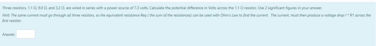
Transcribed Image Text:Three resistors, 1.1 Q. 9.0 2 and 3.2 Q, are wired in series with a power source of 7.3 volts. Calculate the potential difference in Volts across the 1.1 Q resistor. Use 2 significant figures in your answer.
Hint: The same current must go through all three resistors, so the equivalent resistance Reg ( the sum of the resistances) can be used with Ohm's Law to find the current. The current, must then produce a voltage drop I * R1 across the
first resistor.
Answer:
Expert Solution
This question has been solved!
Explore an expertly crafted, step-by-step solution for a thorough understanding of key concepts.

Step by step
Solved in 2 steps with 1 images

Knowledge Booster


Learn more about
Need a deep-dive on the concept behind this application? Look no further. Learn more about this topic, electrical-engineering and related others by exploring similar questions and additional content below.Recommended textbooks for you
Introductory Circuit Analysis (13th Edition)
Electrical Engineering
ISBN:
9780133923605
Author:
Robert L. Boylestad
Publisher:
PEARSON

Delmar's Standard Textbook Of Electricity
Electrical Engineering
ISBN:
9781337900348
Author:
Stephen L. Herman
Publisher:
Cengage Learning

Programmable Logic Controllers
Electrical Engineering
ISBN:
9780073373843
Author:
Frank D. Petruzella
Publisher:
McGraw-Hill Education
Introductory Circuit Analysis (13th Edition)
Electrical Engineering
ISBN:
9780133923605
Author:
Robert L. Boylestad
Publisher:
PEARSON
Delmar's Standard Textbook Of Electricity
Electrical Engineering
ISBN:
9781337900348
Author:
Stephen L. Herman
Publisher:
Cengage Learning
Programmable Logic Controllers
Electrical Engineering
ISBN:
9780073373843
Author:
Frank D. Petruzella
Publisher:
McGraw-Hill Education

Fundamentals of Electric Circuits
Electrical Engineering
ISBN:
9780078028229
Author:
Charles K Alexander, Matthew Sadiku
Publisher:
McGraw-Hill Education

Electric Circuits. (11th Edition)
Electrical Engineering
ISBN:
9780134746968
Author:
James W. Nilsson, Susan Riedel
Publisher:
PEARSON

Engineering Electromagnetics
Electrical Engineering
ISBN:
9780078028151
Author:
Hayt, William H. (william Hart), Jr, BUCK, John A.
Publisher:
Mcgraw-hill Education,