Two identical wood planks are nailed together as shown in the Figure below. Determine the shear resisted by each nail if the applied shear force is 8 kN and the longitudinal spacing between nails is S=8omm 9omm 9omm a =26mm a=26mm
Two identical wood planks are nailed together as shown in the Figure below. Determine the shear resisted by each nail if the applied shear force is 8 kN and the longitudinal spacing between nails is S=8omm 9omm 9omm a =26mm a=26mm

Mechanics of Materials (MindTap Course List)
9th Edition
ISBN:9781337093347
Author:Barry J. Goodno, James M. Gere
Publisher:Barry J. Goodno, James M. Gere
Chapter5: Stresses In Beams (basic Topics)
Section: Chapter Questions
Problem 5.11.12P: Two W 310 × 74 Steel wide-flange beams are bolted together to form a built-up beam as shown in the...

Related questions
Question
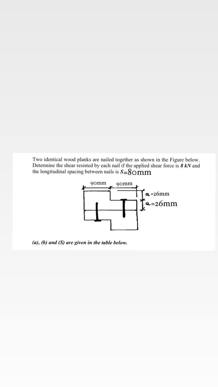
Transcribed Image Text:Two identical wood planks are nailed together as shown in the Figure below.
Determine the shear resisted by each nail if the applied shear force is 8 kN and
the longitudinal spacing between nails is S=8omm
gomm
9omm
a =26mm
a=26mm
(a), (b) and (S) are given in the table below.
Expert Solution
This question has been solved!
Explore an expertly crafted, step-by-step solution for a thorough understanding of key concepts.

Step by step
Solved in 2 steps with 2 images

Recommended textbooks for you
Mechanics of Materials (MindTap Course List)
Mechanical Engineering
ISBN:
9781337093347
Author:
Barry J. Goodno, James M. Gere
Publisher:
Cengage Learning
Mechanics of Materials (MindTap Course List)
Mechanical Engineering
ISBN:
9781337093347
Author:
Barry J. Goodno, James M. Gere
Publisher:
Cengage Learning