Two synchronous generators G1 and G2 are connected to a power transformer Tr and a transmission line as shown below. The system details are as follows: G1: 80 MVA 11KV X” = 20% G2: 60 MVA 11KV X” = 20% Tr. 100 MVA 11/132KV X” = 12% T.L. Xline = j140 Ω a) Draw the system diagram in per unit on a base power =100 MVA and a base voltage =11KV at the generators side. b) Calculate the three-phase balanced short circuit current (If ) at busbar 3 in Ampere at the high voltage side and at the low voltage side of the transformer. c) Calculate the fault level (MVA)sc in MVA at the high voltage side and at the low voltage side of the transformer


Synchronous Generator
In comparison to an asynchronous generator, it is a machine where the rotor speed is equal to the rotating magnetic field produced by the stator, i.e., mechanical speed is equal to the electrical speed, thus called synchronous, and not asynchronous.
Salient Pole Rotor
Salient pole rotor includes a large number of exposed poles mounted on a magnetic wheel. The construction of a bright pole is as shown in the image on the left. The proposed poles are made of metal laminations. The rotor winding is provided on these poles and is supported by pole shoes.
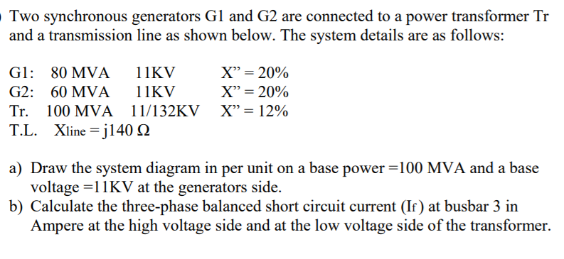
Two synchronous generators G1 and G2 are connected to a power transformer Tr
and a transmission line as shown below. The system details are as follows:
G1: 80 MVA 11KV X” = 20%
G2: 60 MVA 11KV X” = 20%
Tr. 100 MVA 11/132KV X” = 12%
T.L. Xline = j140 Ω
a) Draw the system diagram in per unit on a base power =100 MVA and a base
voltage =11KV at the generators side.
b) Calculate the three-phase balanced short circuit current (If ) at busbar 3 in
Ampere at the high voltage side and at the low voltage side of the transformer.
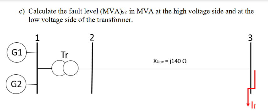
c) Calculate the fault level (MVA)sc in MVA at the high voltage side and at the
low voltage side of the transformer

Step by step
Solved in 5 steps with 4 images


