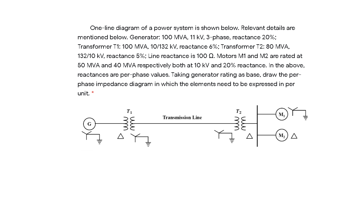
One-line diagram of a power system is shown below. Relevant details are mentioned below. Generator: 100 MVA, 11 kV, 3-phase, reactance 20%; Transformer T1: 100 MVA, 10/132 kV, reactance 6%; Transformer T2: 80 MVA, 132/10 kV, reactance 5%; Line reactance is 100 Q. Motors M1 and M2 are rated at 50 MVA and 40 MVA respectively both at 10 kV and 20% reactance. In the above, reactances are per-phase values. Taking generator rating as base, draw the per- phase impedance diagram in which the elements need to be expressed in per unit. * T1 T2 Transmission Line G M,) A m
One-line diagram of a power system is shown below. Relevant details are mentioned below. Generator: 100 MVA, 11 kV, 3-phase, reactance 20%; Transformer T1: 100 MVA, 10/132 kV, reactance 6%; Transformer T2: 80 MVA, 132/10 kV, reactance 5%; Line reactance is 100 Q. Motors M1 and M2 are rated at 50 MVA and 40 MVA respectively both at 10 kV and 20% reactance. In the above, reactances are per-phase values. Taking generator rating as base, draw the per- phase impedance diagram in which the elements need to be expressed in per unit. * T1 T2 Transmission Line G M,) A m

Power System Analysis and Design (MindTap Course List)
6th Edition
ISBN:9781305632134
Author:J. Duncan Glover, Thomas Overbye, Mulukutla S. Sarma
Publisher:J. Duncan Glover, Thomas Overbye, Mulukutla S. Sarma
Chapter3: Power Transformers
Section: Chapter Questions
Problem 3.49P: Consider the single-Line diagram of a power system shown in Figure 3.42 with equipment ratings...

Related questions

Concept explainers
Three-Phase Transformers
Three-segment transformers are a type of transformer used to transform voltages of electrical systems into three ranges. Two type transformers are shell-type transformer and core type transformer. In brief, it could be described because of the exquisite kinds of configurations.
Transformer
Ever since electricity has been created, people have started using it in its entirety. We see many types of Transformers in the neighborhoods. Some are smaller in size and some are very large. They are used according to their requirements. Many of us have seen the electrical transformer but they do not know what work they are engaged in.
Question
Transcribed Image Text:One-line diagram of a power system is shown below. Relevant details are
mentioned below. Generator: 100 MVA, 11 kV, 3-phase, reactance 20%;
Transformer T1: 100 MVA, 10/132 kV, reactance 6%; Transformer T2: 80 MVA,
132/10 kV, reactance 5%; Line reactance is 100 Q. Motors M1 and M2 are rated at
50 MVA and 40 MVA respectively both at 10 kV and 20% reactance. In the above,
reactances are per-phase values. Taking generator rating as base, draw the per-
phase impedance diagram in which the elements need to be expressed in per
unit. *
T1
M,
Transmission Line
G
M2) A
Expert Solution
This question has been solved!
Explore an expertly crafted, step-by-step solution for a thorough understanding of key concepts.

This is a popular solution!

Trending now
This is a popular solution!

Step by step
Solved in 6 steps with 1 images

Knowledge Booster


Learn more about
Need a deep-dive on the concept behind this application? Look no further. Learn more about this topic, electrical-engineering and related others by exploring similar questions and additional content below.Recommended textbooks for you
Power System Analysis and Design (MindTap Course …
Electrical Engineering
ISBN:
9781305632134
Author:
J. Duncan Glover, Thomas Overbye, Mulukutla S. Sarma
Publisher:
Cengage Learning

Delmar's Standard Textbook Of Electricity
Electrical Engineering
ISBN:
9781337900348
Author:
Stephen L. Herman
Publisher:
Cengage Learning
Power System Analysis and Design (MindTap Course …
Electrical Engineering
ISBN:
9781305632134
Author:
J. Duncan Glover, Thomas Overbye, Mulukutla S. Sarma
Publisher:
Cengage Learning
Delmar's Standard Textbook Of Electricity
Electrical Engineering
ISBN:
9781337900348
Author:
Stephen L. Herman
Publisher:
Cengage Learning