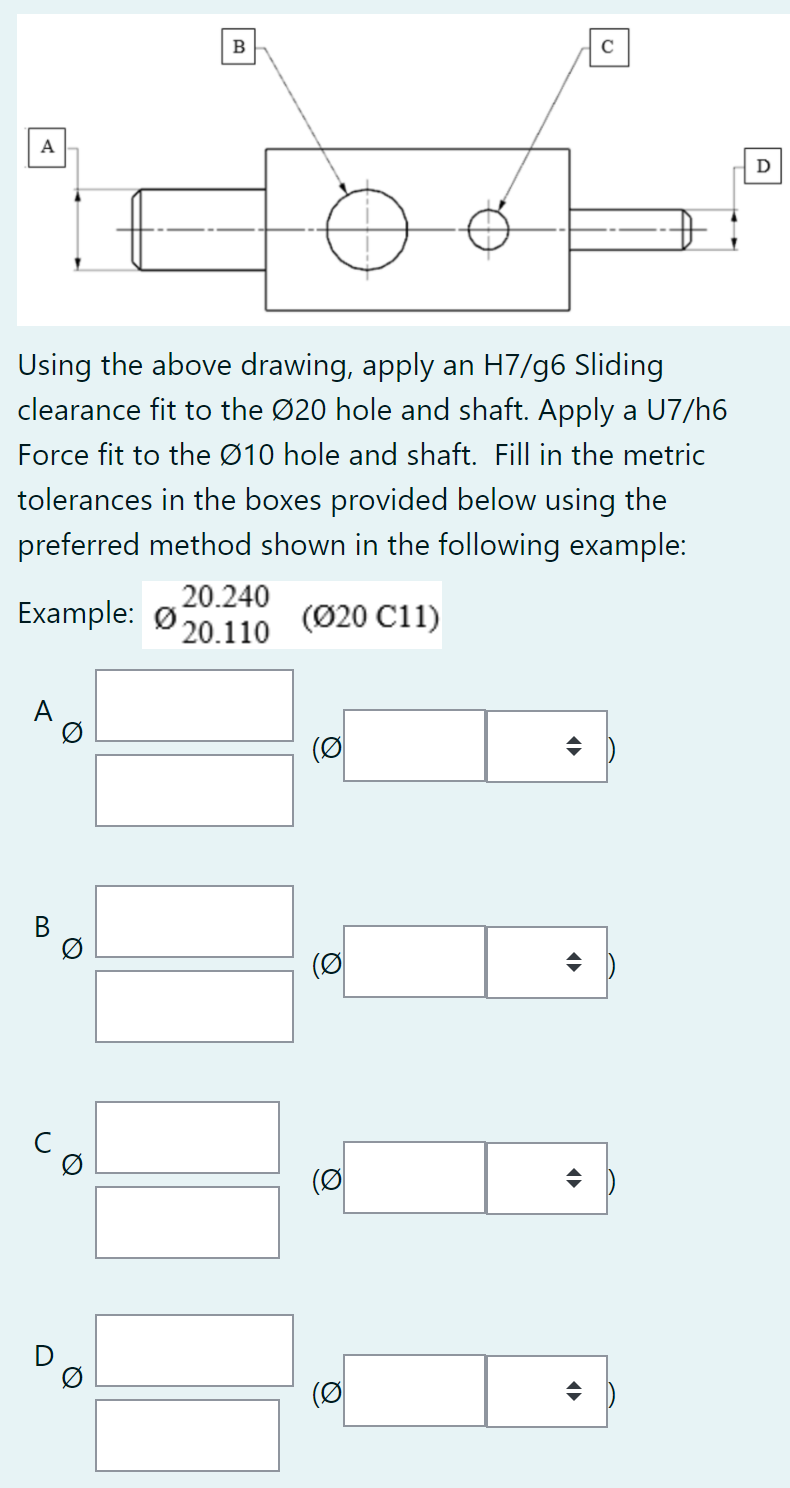
Using the above drawing, apply an H7/g6 Sliding clearance fit to the Ø20 hole and shaft. Apply a U7/h6 Force fit to the Ø10 hole and shaft. Fill in the metric tolerances in the boxes provided below using the preferred method shown in the following example: 20.240 Example: Ø 20.110 (Ø20 C11) A (Ø В Ø (Ø (Ø
Using the above drawing, apply an H7/g6 Sliding clearance fit to the Ø20 hole and shaft. Apply a U7/h6 Force fit to the Ø10 hole and shaft. Fill in the metric tolerances in the boxes provided below using the preferred method shown in the following example: 20.240 Example: Ø 20.110 (Ø20 C11) A (Ø В Ø (Ø (Ø

International Edition---engineering Mechanics: Statics, 4th Edition
4th Edition
ISBN:9781305501607
Author:Andrew Pytel And Jaan Kiusalaas
Publisher:Andrew Pytel And Jaan Kiusalaas
Chapter8: Centroids And Distributed Loads
Section: Chapter Questions
Problem 8.73P

Related questions
Question
Transcribed Image Text:B
C
A
D
Using the above drawing, apply an H7/g6 Sliding
clearance fit to the Ø20 hole and shaft. Apply a U7/h6
Force fit to the Ø10 hole and shaft. Fill in the metric
tolerances in the boxes provided below using the
preferred method shown in the following example:
Example: Ø
20.240
20.110
(Ø20 C11)
A
(이
(이
(이
(이
Q
Q
B.
Expert Solution
This question has been solved!
Explore an expertly crafted, step-by-step solution for a thorough understanding of key concepts.

This is a popular solution!

Trending now
This is a popular solution!

Step by step
Solved in 2 steps with 2 images

Recommended textbooks for you
International Edition---engineering Mechanics: St…
Mechanical Engineering
ISBN:
9781305501607
Author:
Andrew Pytel And Jaan Kiusalaas
Publisher:
CENGAGE L
International Edition---engineering Mechanics: St…
Mechanical Engineering
ISBN:
9781305501607
Author:
Andrew Pytel And Jaan Kiusalaas
Publisher:
CENGAGE L