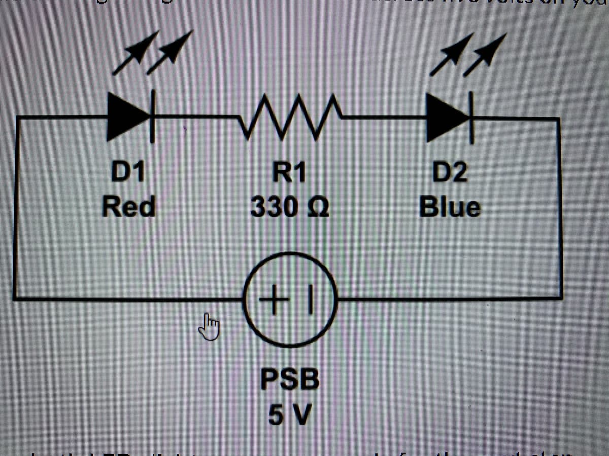
With the negative probe connected to ground, measure and record the following voltages, in reference to ground: • High potential side of D1 - This will give you the voltage across the entire series. Expected value is about 5V. · Between D1 and R1 (you can use the low side of D1 or the high side of R1, since the readings will be the same). Expected value is about 3.3V because the forward voltage of D1 is about 1.7V, leaving 3.3V for the rest of the components in the series. • Between R1 and D2. This will give you the forward voltage of D2 in this series. Expected value is about 2.8V. ince you know the voltage in reference to ground at each point in the series, you can also easily determine the voltage across any individual component. The ground eferenced voltage on the high side of the component, minus the voltage on the low side of that component, will tell you the voltage across the component. You can onfirm the answer by measuring the voltage directly across the component, which should be very close to the same value. The meter rounds values up or down a ttle, so the numbers may not always match exactly, but they should be very close. You will need the voltage across R1 (with D1 and D2 both lit) for the assignment. WARNING: If, at any point in this assignment, the voltage across R1 is zero while the circuit is turned on, this means the resistor has been shorted and you risk burning out D1 or damaging D2. Make sure R1 is not shorted.


Protection System
A system that protects electrical systems from faults by isolating the problematic part from the remainder of the system, preventing power from being cut from healthy elements, improving system dependability and efficiency is the protection system. Protection devices are the equipment that are utilized to implement the protection system.
Predictive Maintenance System
Predictive maintenance technologies are designed to assist in determining the state of in-service equipment so that maintenance can be scheduled. Predictive maintenance is the application of information; proactive maintenance approaches examine the condition of equipment and anticipate when it should maintain. The purpose of predictive maintenance is to forecast when equipment will fail (depending on a variety of parameters), then prevent the failure through routine and corrective maintenance.Condition monitoring is the continual monitoring of machines during process conditions to maintain optimal machine use, which is necessary for predictive maintenance. There are three types of condition monitoring: online, periodic, and remote. Finally, remote condition monitoring allows the equipment observed from a small place and data supplied for analysis.
Preventive Maintenance System
To maintain the equipment and materials on a regular basis in order to maintain those running conditions and reduce unnecessary shutdowns due to unexpected equipment failure is called Preventive Maintenance (PM).


Trending now
This is a popular solution!

Step by step
Solved in 2 steps with 4 images

How much current is flowing through the circuit?


