You are tasked to look for a converter circuit design that has the specifications tabulated in Table I. The aim is to produce an output voltage of 20 V which can be used to drive a load of 120 W. The converter must operate in CCM. Design Parameters Input voltage Switching frequency Output current ripple Output voltage ripple Table I: Design Specifications Values 35 V 60 kHz 5 % 1 % a) Sketch the final converter and label all parameter values b) Sketch the final operating waveforms and label all parameter values c) Determine Vamin and Va,max- Check if the output voltage ripple matches with the design requirement.
You are tasked to look for a converter circuit design that has the specifications tabulated in Table I. The aim is to produce an output voltage of 20 V which can be used to drive a load of 120 W. The converter must operate in CCM. Design Parameters Input voltage Switching frequency Output current ripple Output voltage ripple Table I: Design Specifications Values 35 V 60 kHz 5 % 1 % a) Sketch the final converter and label all parameter values b) Sketch the final operating waveforms and label all parameter values c) Determine Vamin and Va,max- Check if the output voltage ripple matches with the design requirement.

Introductory Circuit Analysis (13th Edition)
13th Edition
ISBN:9780133923605
Author:Robert L. Boylestad
Publisher:Robert L. Boylestad
Chapter1: Introduction
Section: Chapter Questions
Problem 1P: Visit your local library (at school or home) and describe the extent to which it provides literature...

Related questions

Question
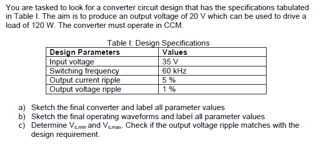
Transcribed Image Text:You are tasked to look for a converter circuit design that has the specifications tabulated
in Table I. The aim is to produce an output voltage of 20 V which can be used to drive a
load of 120 W. The converter must operate in CCM.
Table I: Design Specifications
Design Parameters
Input voltage
Switching frequency
Output current ripple
Output voltage ripple
Values
35 V
60 kHz
5 %
1%
a) Sketch the final converter and label all parameter values
b) Sketch the final operating waveforms and label all parameter values
c) Determine Ve.min and Vemax- Check if the output voltage ripple matches with the
design requirement.
Expert Solution
This question has been solved!
Explore an expertly crafted, step-by-step solution for a thorough understanding of key concepts.

Step by step
Solved in 4 steps with 5 images

Knowledge Booster


Learn more about
Need a deep-dive on the concept behind this application? Look no further. Learn more about this topic, electrical-engineering and related others by exploring similar questions and additional content below.Recommended textbooks for you
Introductory Circuit Analysis (13th Edition)
Electrical Engineering
ISBN:
9780133923605
Author:
Robert L. Boylestad
Publisher:
PEARSON

Delmar's Standard Textbook Of Electricity
Electrical Engineering
ISBN:
9781337900348
Author:
Stephen L. Herman
Publisher:
Cengage Learning

Programmable Logic Controllers
Electrical Engineering
ISBN:
9780073373843
Author:
Frank D. Petruzella
Publisher:
McGraw-Hill Education
Introductory Circuit Analysis (13th Edition)
Electrical Engineering
ISBN:
9780133923605
Author:
Robert L. Boylestad
Publisher:
PEARSON
Delmar's Standard Textbook Of Electricity
Electrical Engineering
ISBN:
9781337900348
Author:
Stephen L. Herman
Publisher:
Cengage Learning
Programmable Logic Controllers
Electrical Engineering
ISBN:
9780073373843
Author:
Frank D. Petruzella
Publisher:
McGraw-Hill Education

Fundamentals of Electric Circuits
Electrical Engineering
ISBN:
9780078028229
Author:
Charles K Alexander, Matthew Sadiku
Publisher:
McGraw-Hill Education

Electric Circuits. (11th Edition)
Electrical Engineering
ISBN:
9780134746968
Author:
James W. Nilsson, Susan Riedel
Publisher:
PEARSON

Engineering Electromagnetics
Electrical Engineering
ISBN:
9780078028151
Author:
Hayt, William H. (william Hart), Jr, BUCK, John A.
Publisher:
Mcgraw-hill Education,