11. A Zener diode is connected in a voltage regulator circuit as shown in Figure Q9. The Zener voltage is Vz 10 V and the Zener resistance is assumed to be rz = 0. (a) Determine the value of R such that the Zener diode remains in breakdown if the load current varies from I = 50 to 500 mA and if the input voltage varies from V = 15 to 20 V. Assume Iz (min) = 0.1Iz (max). (b) Determine the power rating required for the Zener diode and the load resistor.
11. A Zener diode is connected in a voltage regulator circuit as shown in Figure Q9. The Zener voltage is Vz 10 V and the Zener resistance is assumed to be rz = 0. (a) Determine the value of R such that the Zener diode remains in breakdown if the load current varies from I = 50 to 500 mA and if the input voltage varies from V = 15 to 20 V. Assume Iz (min) = 0.1Iz (max). (b) Determine the power rating required for the Zener diode and the load resistor.

Chapter59: Motor Startup And Troubleshooting Basics
Section: Chapter Questions
Problem 12SQ: How is a solid-state diode tested? Explain.

Related questions

Question
Solution to question 11 and 12 in the image below
Transcribed Image Text:Iz
VI
R VL
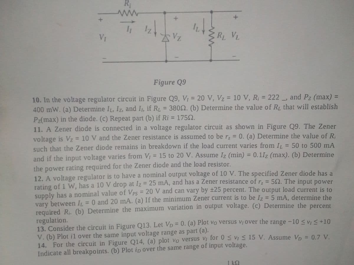
Figure Q9
and Pz (max) =
10. In the voltage regulator circuit in Figure Q9, V, = 20 V, Vz = 10 V, R; = 222
400 mW. (a) Determine IL, Iz, and I, if RL = 3802. (b) Determine the value of RL that will establish
Pz(max) in the diode. (c) Repeat part (b) if Ri = 1752.
11. A Zener diode is connected in a voltage regulator circuit as shown in Figure Q9. The Zener
voltage is Vz = 10 V and the Zener resistance is assumed to be r, = 0. (a) Determine the value of R;
such that the Zener diode remains in breakdown if the load current varies from IL = 50 to 500 mA
and if the input voltage varies from V = 15 to 20 V. Assume Iz (min) = 0.1Iz (max). (b) Determine
%3D
%3D
%3D
%3D
%3D
%3D
%3D
the power rating required for the Zener diode and the load resistor.
12. A voltage regulator is to have a nominal output voltage of 10 V. The specified Zener diode has a
rating of 1 W, has a 10 V drop at Iz = 25 mA, and has a Zener resistance of rz = 52. The input power
supply has a nominal value of VPs = 20 V and can vary by ±25 percent. The output load current is to
vary between I = 0 and 20 mA. (a) If the minimum Zener current is to be Iz = 5 mA, determine the
required R. (b) Determine the maximum variation in output voltage. (c) Determine the percent
regulation.
13. Consider the circuit in Figure Q13. Let VD = 0. (a) Plot vo Versus Vị over the range -10 <v <+10
V. (b) Plot i1 over the same input voltage range as part (a).
14. For the circuit in Figure Q14, (a) plot vo versus Vị for 0 vi < 15 V. Assume Vp = 0.7 V.
Indicate all breakpoints. (b) Plot ip over the same range of input voltage.
%3D
%3D
%3D
1 k2
Expert Solution
This question has been solved!
Explore an expertly crafted, step-by-step solution for a thorough understanding of key concepts.

This is a popular solution!

Trending now
This is a popular solution!

Step by step
Solved in 3 steps

Knowledge Booster


Learn more about
Need a deep-dive on the concept behind this application? Look no further. Learn more about this topic, electrical-engineering and related others by exploring similar questions and additional content below.Recommended textbooks for you

Electricity for Refrigeration, Heating, and Air C…
Mechanical Engineering
ISBN:
9781337399128
Author:
Russell E. Smith
Publisher:
Cengage Learning

Delmar's Standard Textbook Of Electricity
Electrical Engineering
ISBN:
9781337900348
Author:
Stephen L. Herman
Publisher:
Cengage Learning
Electricity for Refrigeration, Heating, and Air C…
Mechanical Engineering
ISBN:
9781337399128
Author:
Russell E. Smith
Publisher:
Cengage Learning
Delmar's Standard Textbook Of Electricity
Electrical Engineering
ISBN:
9781337900348
Author:
Stephen L. Herman
Publisher:
Cengage Learning