CIS 256 Lab 8 - Configuring Cisco Router with RIP Protocol
docx
keyboard_arrow_up
School
Community College of Philadelphia *
*We aren’t endorsed by this school
Course
256
Subject
Computer Science
Date
Apr 3, 2024
Type
docx
Pages
7
Uploaded by thebigd130
Your preview ends here
Eager to read complete document? Join bartleby learn and gain access to the full version
- Access to all documents
- Unlimited textbook solutions
- 24/7 expert homework help
Your preview ends here
Eager to read complete document? Join bartleby learn and gain access to the full version
- Access to all documents
- Unlimited textbook solutions
- 24/7 expert homework help
Recommended textbooks for you

A+ Guide To It Technical Support
Computer Science
ISBN:9780357108291
Author:ANDREWS, Jean.
Publisher:Cengage,

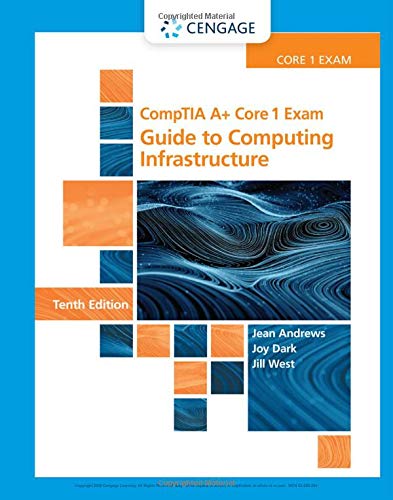
Comptia A+ Core 1 Exam: Guide To Computing Infras...
Computer Science
ISBN:9780357108376
Author:Jean Andrews, Joy Dark, Jill West
Publisher:Cengage Learning

Fundamentals of Information Systems
Computer Science
ISBN:9781337097536
Author:Ralph Stair, George Reynolds
Publisher:Cengage Learning

A+ Guide to Hardware (Standalone Book) (MindTap C...
Computer Science
ISBN:9781305266452
Author:Jean Andrews
Publisher:Cengage Learning

Systems Architecture
Computer Science
ISBN:9781305080195
Author:Stephen D. Burd
Publisher:Cengage Learning

Principles of Information Systems (MindTap Course...
Computer Science
ISBN:9781285867168
Author:Ralph Stair, George Reynolds
Publisher:Cengage Learning
Recommended textbooks for you
 A+ Guide To It Technical SupportComputer ScienceISBN:9780357108291Author:ANDREWS, Jean.Publisher:Cengage,
 Comptia A+ Core 1 Exam: Guide To Computing Infras...Computer ScienceISBN:9780357108376Author:Jean Andrews, Joy Dark, Jill WestPublisher:Cengage Learning
 Fundamentals of Information SystemsComputer ScienceISBN:9781337097536Author:Ralph Stair, George ReynoldsPublisher:Cengage Learning
 A+ Guide to Hardware (Standalone Book) (MindTap C...Computer ScienceISBN:9781305266452Author:Jean AndrewsPublisher:Cengage Learning
 Systems ArchitectureComputer ScienceISBN:9781305080195Author:Stephen D. BurdPublisher:Cengage Learning
 Principles of Information Systems (MindTap Course...Computer ScienceISBN:9781285867168Author:Ralph Stair, George ReynoldsPublisher:Cengage Learning

A+ Guide To It Technical Support
Computer Science
ISBN:9780357108291
Author:ANDREWS, Jean.
Publisher:Cengage,

Comptia A+ Core 1 Exam: Guide To Computing Infras...
Computer Science
ISBN:9780357108376
Author:Jean Andrews, Joy Dark, Jill West
Publisher:Cengage Learning

Fundamentals of Information Systems
Computer Science
ISBN:9781337097536
Author:Ralph Stair, George Reynolds
Publisher:Cengage Learning

A+ Guide to Hardware (Standalone Book) (MindTap C...
Computer Science
ISBN:9781305266452
Author:Jean Andrews
Publisher:Cengage Learning

Systems Architecture
Computer Science
ISBN:9781305080195
Author:Stephen D. Burd
Publisher:Cengage Learning

Principles of Information Systems (MindTap Course...
Computer Science
ISBN:9781285867168
Author:Ralph Stair, George Reynolds
Publisher:Cengage Learning