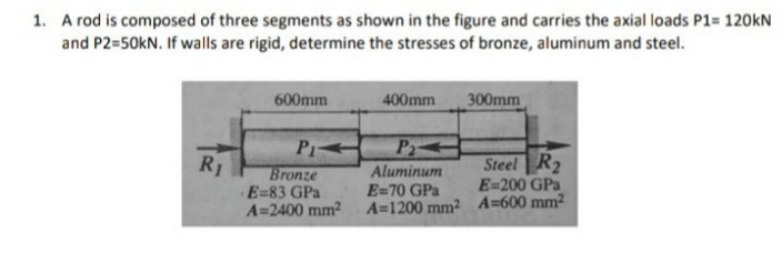
.A rod is composed of three segments as shown in the figure and carries the axial loads P1= 120kN and P2=50KN. If walls are rigid, determine the stresses of bronze, aluminum and steel. 600mm 400mm 300mm Pr R1 Bronze E=83 GPa A=2400 mm? Aluminum E=70 GPa A=1200 mm2 A=600 mm2 Steel R2 E=200 GPa
Q: Q1/A steel bar ABCD (4m) long is subjected to forces as shown in Figure. Find the stresses in each…
A:
Q: Forces of F1=7 kN in the +y direction and F2=13 kN in the -z direction are acting on the arm from…
A: Given data, Force F1 = 7 kN Force F2 = 13 kN Moment M = 4 kNm Arm length, L1 = 0.8 m Arm length, L2…
Q: A steel rod of 20 mm diameter passes centrally through a copper tube of external diameter 40 mm and…
A:
Q: 1. A rod is composed of three segments as shown in the figure and carries the axial loads P1= 120KN…
A:
Q: For the assembly shown in the figure below, Determine the state of stress at point A on the cross…
A: To find: The state of stress at point A on the cross section of pipe at section a-a. Given: The…
Q: F1. The rigid bar ABC in the figure is supported by a clevis and pin at its right hand side and by…
A: Draw the free-body diagram of the beam.
Q: The solid shaft shown in the figure below is fixed at one end and has a lever at the other. The…
A:
Q: A steel bar with a diameter of 100 mm is rigidly attached to the wall and carries the loads shown in…
A: Given: The diameter of shaft, d = 100 mm = 0.1 m The torque acting on the shaft, T = 8 kN.m The load…
Q: A solid circular composite bar (made of aluminum in segment AB, steel in segment BC and Brass in…
A:
Q: For a closed end cylinder where the inner radius is 20 mm and outer radius is 40 mm, and the…
A: Sddd
Q: Rigid bar BC is supported by aluminum rod (1) and bronze rod (2), as shown in the figure. Aluminum…
A:
Q: 10 KN 20 KN / m 5 KN / m A B SIMPLE STRESSES 5 KN / m D 5 KN / m F 50 KN-m E 3. Points C and D of…
A: Given DataP=10kNw1=5kN/mw2=20kN/m
Q: Q3 - A thin-walled cylindrical vessel has an internal diameter of 1m and a thickness of 10 mm…
A: pressure:- Pressure is defined as the physical force exerted on an object. The force applied is…
Q: A solid bar has a diameter of 40 mm and subjected to the loadings shown in Figure 2. The supports at…
A:
Q: A clevis-type pipe hanger supports an 8-in.-diameter pipe, as shown in Figure. The hanger rod has a…
A: Given data: W=2000 lb Need to determine the normal stress in the hanger rod, shear stress in the…
Q: Q1. A compound bar consists of a circular rod of steel of 25 mm diameter rigidly fixéd Into a copper…
A: The given area of the circular rod is given below.
Q: A two-step bar subjected to loading condition as shown in below figure is fixed at one end and the…
A:
Q: Neglecting the weight of the bar as shown in the figure, determine the stress in each rod if the…
A:
Q: A three segments of steel rods, is shown in the following Figure. Each rod has a diameter as shown…
A:
Q: The given system below, consisting of a rigid horizontal bar ABC and supported by three vertical…
A: Given data: - The diameter of rod B is DB = 26 mm. The length of rod B is LB = 4400 mm. The…
Q: Rigid bar ABC shown in the figure is supported by a pin at bracket A and by tie rod (1). Tie rod (1)…
A:
Q: A bolted connection between a vertical column and a diagonal brace is shown in the figure below. The…
A:
Q: Q3. Two bars of rectangular cross section (thickness t=15 mm) are connected by a bolt in the manner…
A: Given : P = 31 KN thickness, t of the base = 15mm Allowable shear stress in bolt ζAllow = 90 MPa…
Q: A circular rod of a diameter of 100 mm is subjected at its free end to force F1 = 50N and F2=(200j -…
A: In this question, three forces are given. The forces are Point force, F1=50i kN Point force,…
Q: A circular bracket with a diameter of 100 mm is fixed to a wall as shown in the figure below.…
A:
Q: The tank shown in the figure shown is fabricated from a steel plate. a. Determine the maximum…
A:
Q: The machine component shown in Figure below is subjected to a load P = 450 lb that acts at an angle…
A:
Q: 7.4-17 A sign is supported by a pole of hollow circular cross section, as shown in the figure. The…
A: Given: The outer diameter of pole, D = 10.5 in The inner diameter of pole, d = 8.5 in The height of…
Q: - A member ABCD is subjected to point loads Pi and Pa with magnitudes of 5 kN and 12 kN respectively…
A: There are three members connected in series. Since the both ends are subjected to forces of…
Q: A rod is composed of copper and steel section rigidly bolted in the wall as shown in the figure. If…
A:
Q: A short column with a wide-flange shape is subjected to a compressive load that produces a resultant…
A:
Q: Column is manufactured using concrete (E=4.2×10^3 ksi) and reinforcement is done by A-36 steel rods…
A:
Q: A solid circular composite bar (made of aluminum in segment AB, steel in segment BC and Brass in…
A:
Q: Determine the maximum weight of the lamp that the cables shown in figure can support. The stresses…
A:
Q: A clevis-type pipe hanger supports an 8-in.-diameter pipe, as shown in Figure. The hanger rod has a…
A: Given data: W=2000 lb Need to determine the normal stress in the hanger rod, the shear stress in the…
Q: O1: Two steel pipes [E =200 GPa], each with a cross- sectional area of 1475 mm', are attached to…
A: GIVEN DATA AREA A=1475 mm2 E=200GPa LOAD=120KN WE HAVE TO FIND STRESS IN BOTH PIPES
Q: Question 2) Forces of F1=7 kN in the +y direction and F2=13 kN in the -z direction are acting on the…
A: Given: The force in +y direction, F1 = 7 kN The force in –z direction, F2 = 13 kN The magnitude of…
Q: Q70: For the truss shown in the Figure, if the diameter of pins at A and E are 60mm and 80mm,…
A:
Q: 1. A rod is composed of three segments as shown in the figure and carries the axial loads P1= 120kN…
A:
Q: A uniform bar AB weighing 500 kg is supported at both end by a cable as shown in the figure.…
A:
Q: The yoke and rod connection assembly shown in the figure below is subjected to a tensile force of 5…
A: For the given universal joint it is required to determine: 2.1 tensile stress in each rod 2.2 shear…
Q: For the assembly, find the stress in each rod if the temperature rises 30°C after a load W 120 kN is…
A:
Q: Q8(0: For the truss shown in the Figure, if the diameter of pins at A and G are 3 in and 2 in,…
A: Given: dA = 3 in. dG = 2 in. To find: shear stress in pins A and G. Stresses in the members AG,…
Q: A steel column of hollow circular cross section shown in Figure is supported on a circular steel…
A:
Q: 5. Segment AB of the bar is a tube with an outer diameter of d1 and a wall thickness of 0.125 in.…
A: Given Allowable stress in rod AB = 3400 psi Outer diameter = d1 Inner diameter = d1 - 0.125…
Q: Axial loads are applied with rigid bearing plates to the solid cylindrical rods shown in the figure.…
A:
Q: Rigid bar ABC shown in the figure is supported by a pin at bracket A and by tie rod (1). Tie rod (1)…
A:
Q: A three-member plane truss is shown in the figure. Member (2) has a cross section of 400 mm? and is…
A: Given: Member 2 is made of steel and its specification are A=400 mm2 ,E=210 GPa. While for member 1…
Q: A uniform bar AB weighing 500 kg is supported at both end by a cable as shown in the figure.…
A:
Q: Find the stresses in each section and total change in length of the bar as shown in figure. The bar…
A:
Answer completely about Stress and Strain
Trending now
This is a popular solution!
Step by step
Solved in 4 steps with 4 images
- The hollow drill pipe for an oil well (sec figure) is 6,2 in. in outer diameter and 0.75 in. in thickness. Just above the bit, the compressive force in the pipe (due to the weight of the pipe) is 62 kips and the torque (due to drilling) is 185 kip-in. Determine the maximum tensile, compressive, and shear stresses in the drill pipe.A traffic light and signal pole is subjected to the weight of each traffic signal We = 45 lb and the weight of the road lamp WL= 55 lb. The pole is fixed at the base. Find the principal normal stresses and the maximum shear stress on element B located 19 ft above the base (see figure). Assume that the weight of the pole and lateral arms is included in the signal and lamp weightsSolve the preceding problem if the norm al and shear stresses acting on the element are sx = 2100 kPa, sy= 300 kPa, and txy= -560 kPa, and the seam is oriented at an angle of 22.5° to the clement.
- • - 7.4-7 An element on the surface of a drive shaft is in pure shear and is subjected to stresses ??xy= 2700 psi, as shown in the figure. Using Mohr’s circle, determine the following. (a) The stresses acting on an element oriented at a counterclockwise angle ?= 52° from the y axis. (b) The principal stresses. Show all results on sketches of properly oriented elements.An elevated jogging track is supported at intervals by a wood beam AB (L = 7.5 ft) that is pinned at A and supported by steel rod BC and a steel washer at B. Both the rod (dBC= 3/16 in.) and the washer (dB= 1.0 in.) were designed using a rod tension force of TBC=415 lb. The rod was sized using a factor of safely of 3 against reaching the ultimate stress tru— 60 ksi. An allowable bearing stress sba= 565 psi was used to size the washer at B. A small platform HF is suspended below a section of the elevated track to support some mechanical and electrical equipment. The equipment load is uniform load q = 50 lb/ft and concentrated load WE= 175 lb at mid-span of beam HF. The plan is to drill a hole through beam ABaX £land install the same rod (dBC) and washer) dB) at both D and F to support beam HF. (a) Use s and to check the proposed design for rod DF and washer d,: are they acceptable? (b) Re-check the normal tensile stress in rod BC and bearing stress at 8 if either is inadequate under the additional load from platform HF. Re-design them to meet the original design criteria.A hollow, circular, cast-iron pipe (Ec =12,000 ksi) supports a brass rod (Ec= 14,000 ksi} and weight W — 2 kips, as shown. The outside diameter of the pipe is dc= 6 in. (a) If the allowable compressive stress in the pipe is S00O psi and the allowable shortening of the pipe is 0.02 in., what is the minimum required wall thickness trmm? (Include the weights of the rod and steel cap in your calculations.) (b) What is the elongation of the brass rod Srdue to both load Wand its own weight? (c) What is the minimum required clearance h?
- A short column constructed of a W 12 × 35 wide-flange shape is subjected to a resultant compressive load P = 25 k having its line of action at the midpoint of one flange (see figure). Determine the maximum tensile and compressive stresses d1and d2., respectively, in the column. Locate the neutral axis under this loading condition. Recompute maximum tensile and compressive stresses if a C 10 × 15.3 is attached to one flange, as shown.The flat bars shown in parts a and b of the figure are subjected to tensile forces P = 2.5 kN. Each bar has thickness t = 5.0 mm. (a) For the bar with a circular hole, determine the maximum stresses for hole diameters d = 12 mm and d = 20 mm il" the width h = 60 mm. (b) For the stepped bar with shoulder fillets, determine the maximum stresses Tor fillet radii R = 6 mm and R = 10 mm if the bar widths are h = 60 mm and c = 40 mm.An element on the top surface of the fuel tanker in Problem 7.2-1 is in biaxial stress and is subjected to stresses a = -48 MPa and ay = 19 MPa, as shown in the figure. Using Mohr’s circle, determine the following. (a) The stresses acting on an clement oriented at a counterclockwise angle ?? = 25° from the x axis. (b) The maximum shear stresses and associated normal stresses. Show all results on sketches of properly oriented elements.
- An element on the top surface of the fuel tanker in Problem 7.2-1 is in biaxial .is in the and is subjected to stresses a, = 6250 psi and a. = -1750 psi, as shown in the figure. Using Mohr s circle, determine the following: (a) The stresses acting on an element oriented at a counterclockwise angle ? = 550 from the x axis. (b) The maximum shear stresses and associated norm al stresses. Show all results on sketches of properly oriented elements.The flat bars shown in parts a and b of the figure are subjected to tensile forces P = 3.0 kips. Each bar a has thickness t = 0.25 in. (a) For the bar with a circular hole, determine the maximum stresses for hole diameters d = 1 in. and d = 2 in. if the width b = 6.0 in. (b) For the stepped bar with shoulder fillets, determine the maximum stresses for fillet radii R = 0.25 in. and R = 0.5 in. if the bar widths are b = 4.0 in. and c = 2.5 in.The stresses acting on an element are x= 750 psi, y= 600 psi, and xy = 400 psi. Determine the principal stresses and show them on a sketch of a properly oriented element.