
Introductory Circuit Analysis (13th Edition)
13th Edition
ISBN: 9780133923605
Author: Robert L. Boylestad
Publisher: PEARSON
expand_more
expand_more
format_list_bulleted
Related questions
Question
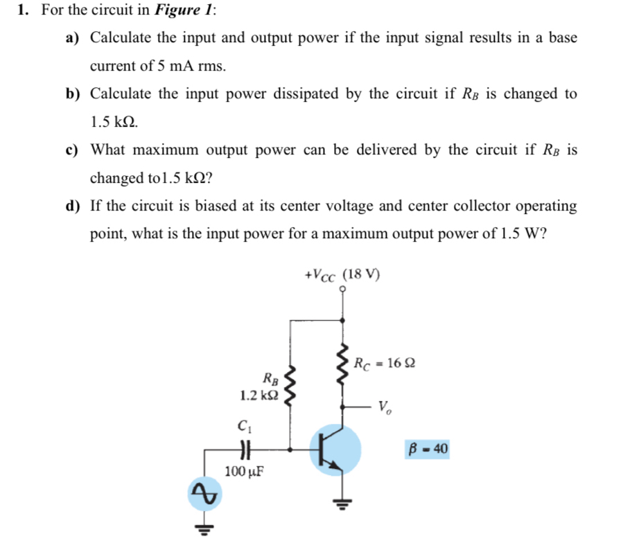

Transcribed Image Text:1. For the circuit in Figure 1:
a) Calculate the input and output power if the input signal results in a base
current of 5 mA rms.
b) Calculate the input power dissipated by the circuit if RB is changed to
1.5 kN.
c) What maximum output power can be delivered by the circuit if RB is
changed to 1.5 kN?
d) If the circuit is biased at its center voltage and center collector operating
point, what is the input power for a maximum output power of 1.5 W?
+Vcc (18 V)
RC -16Ω
RB
1.2 k2
B - 40
100 µF
Expert Solution
This question has been solved!
Explore an expertly crafted, step-by-step solution for a thorough understanding of key concepts.

This is a popular solution

Trending nowThis is a popular solution!

Step by stepSolved in 4 steps with 4 images

Knowledge Booster


Learn more about
Need a deep-dive on the concept behind this application? Look no further. Learn more about this topic, electrical-engineering and related others by exploring similar questions and additional content below.Similar questions
- Please answer with details on how to do it. Thank youarrow_forwardYou are an electrician working on an overhead crane. The crane uses a large electromagnet to pick up large metal pipes. The magnet must have a minimum of 200 VDC to operate properly. The crane has an AC source of 240 V. You are given four diodes that have a peak voltage rating of 400 V each. These diodes are to be used to form a bridge rectifier to convert the AC voltage into DC voltage. Is the voltage rating of the diodes sufficient? To the nearest volt, what will be the DC output voltage of the bridge rectifier?arrow_forwardA buck-boost converter operates with an input battery. It converts +12 V to –12 V at apower level of about 75 W. the switching frequency is 120 kHz. The switches have200 ns switching time. The battery has an internal series resistance of 0.2 and seriesinductance of 200 nH. (a) What is the operating value of the duty ratio? What power is lost in the battery resistance? (b) Propose an interface structure to improve operation and decrease losses. What are the duty ratio and battery resistance loss with your interface in place?arrow_forward
- A 60 Hz sinusoidal voltage is applied to an SCR full-wave rectifier. If the DC output voltage is 162 V and the firing angle of the SCR is 60 degrees, the peak voltage of the input sinusoidal would be: O A. 197 V O B. 228 V O C. Can't tell; need more information. O D. 340 V O E. None of the other choices are correctarrow_forwardYou are an electrician working on an overhead crane. The crane uses a large electromagnet to pick up large metal pipes. The magnet must have a minimum of 200 VDC to operate properly. The crane has an AC source of 240 V. You are given four diodes that have a peak voltage rating of 400 V each. These diodes are to be used to form a bridge rectifier to convert the AC voltage into DC voltage. Is the voltage rating of the diodes sufficient? To the nearest volt, what will be the DC output voltage of the bridge rectifier?arrow_forwardDesign the Clipper-Clamper circuit to perform the output waveform shown in figure below.arrow_forward
- 18. A dc-dc converter is to be built with the following specifications: Allowed dc input voltage range: +8 V to +18 V +24 V Output average voltage: Output voltage ripple: ±0.06 V maximum at rated load 300 W, resistive ±250 mA maximum at rated load 100 kHz Rated load: Input current ripple: Switching frequency: Common ground between input and output. a. Draw a circuit which can perform this function. b. What is the necessary range of duty ratio for each switch? c. Find circuit part values (R, L, and C) which will meet the stated specifications.arrow_forwardSub:power electricarrow_forwardThe input to a full-wave rectifier is 10 V AC (RMS). The load resistor is 10 ohms and rectifier losses are 4W. The power efficiency of the rectifier is: O A. 58 % O B. None of the other choices are correct O C. 100 % O D. 80 % O E. 67 %arrow_forward
arrow_back_ios
arrow_forward_ios
Recommended textbooks for you
- Introductory Circuit Analysis (13th Edition)Electrical EngineeringISBN:9780133923605Author:Robert L. BoylestadPublisher:PEARSON
 Delmar's Standard Textbook Of ElectricityElectrical EngineeringISBN:9781337900348Author:Stephen L. HermanPublisher:Cengage Learning
 Programmable Logic ControllersElectrical EngineeringISBN:9780073373843Author:Frank D. PetruzellaPublisher:McGraw-Hill Education
  Fundamentals of Electric CircuitsElectrical EngineeringISBN:9780078028229Author:Charles K Alexander, Matthew SadikuPublisher:McGraw-Hill Education
 Electric Circuits. (11th Edition)Electrical EngineeringISBN:9780134746968Author:James W. Nilsson, Susan RiedelPublisher:PEARSON
 Engineering ElectromagneticsElectrical EngineeringISBN:9780078028151Author:Hayt, William H. (william Hart), Jr, BUCK, John A.Publisher:Mcgraw-hill Education,
Introductory Circuit Analysis (13th Edition)
Electrical Engineering
ISBN:9780133923605
Author:Robert L. Boylestad
Publisher:PEARSON
Delmar's Standard Textbook Of Electricity
Electrical Engineering
ISBN:9781337900348
Author:Stephen L. Herman
Publisher:Cengage Learning
Programmable Logic Controllers
Electrical Engineering
ISBN:9780073373843
Author:Frank D. Petruzella
Publisher:McGraw-Hill Education
Fundamentals of Electric Circuits
Electrical Engineering
ISBN:9780078028229
Author:Charles K Alexander, Matthew Sadiku
Publisher:McGraw-Hill Education
Electric Circuits. (11th Edition)
Electrical Engineering
ISBN:9780134746968
Author:James W. Nilsson, Susan Riedel
Publisher:PEARSON
Engineering Electromagnetics
Electrical Engineering
ISBN:9780078028151
Author:Hayt, William H. (william Hart), Jr, BUCK, John A.
Publisher:Mcgraw-hill Education,