Part A - Calculating the output voltage of a difference op-amp circuit Learning Goal: To analyze difference op-amp circuits. Before proceeding, review difference op-amp circuits and the For the circuit shown (Figure 1). determine Vo when R1 = 9.6 kN, R2 = 40 kN. V = 10 mV, Vy = 40 mV, and Ver = 5 V ideal op-amp assumptions. Express your answer to three significant tigures and include the appropriate units. > View Available Hint(s) ? Vo = Value Units Submit Part B - Design of a difference op-amp circuit For the circuit shown (Figure 1), determine R1 such that Vo = m x (Vz - Vy) - Assume m = 4.5 and R2 = 30 k2 and that the op-amp is in its linear region of operation. Figure 1 of 1 Express your answer to three significant figures. > View Available Hint(s) IVol AEO It vec ? V. R R = -V V. Submit R2 Provide Feedback Next > 2 Pearson
Part A - Calculating the output voltage of a difference op-amp circuit Learning Goal: To analyze difference op-amp circuits. Before proceeding, review difference op-amp circuits and the For the circuit shown (Figure 1). determine Vo when R1 = 9.6 kN, R2 = 40 kN. V = 10 mV, Vy = 40 mV, and Ver = 5 V ideal op-amp assumptions. Express your answer to three significant tigures and include the appropriate units. > View Available Hint(s) ? Vo = Value Units Submit Part B - Design of a difference op-amp circuit For the circuit shown (Figure 1), determine R1 such that Vo = m x (Vz - Vy) - Assume m = 4.5 and R2 = 30 k2 and that the op-amp is in its linear region of operation. Figure 1 of 1 Express your answer to three significant figures. > View Available Hint(s) IVol AEO It vec ? V. R R = -V V. Submit R2 Provide Feedback Next > 2 Pearson

Delmar's Standard Textbook Of Electricity
7th Edition
ISBN:9781337900348
Author:Stephen L. Herman
Publisher:Stephen L. Herman
Chapter18: Resistive-inductive Parallel Circuits
Section: Chapter Questions
Problem 13PP: In an R-L parallel circuit, IT=1.25 amps, R=1.2k, and XL=1k. Find IR

Related questions

Question
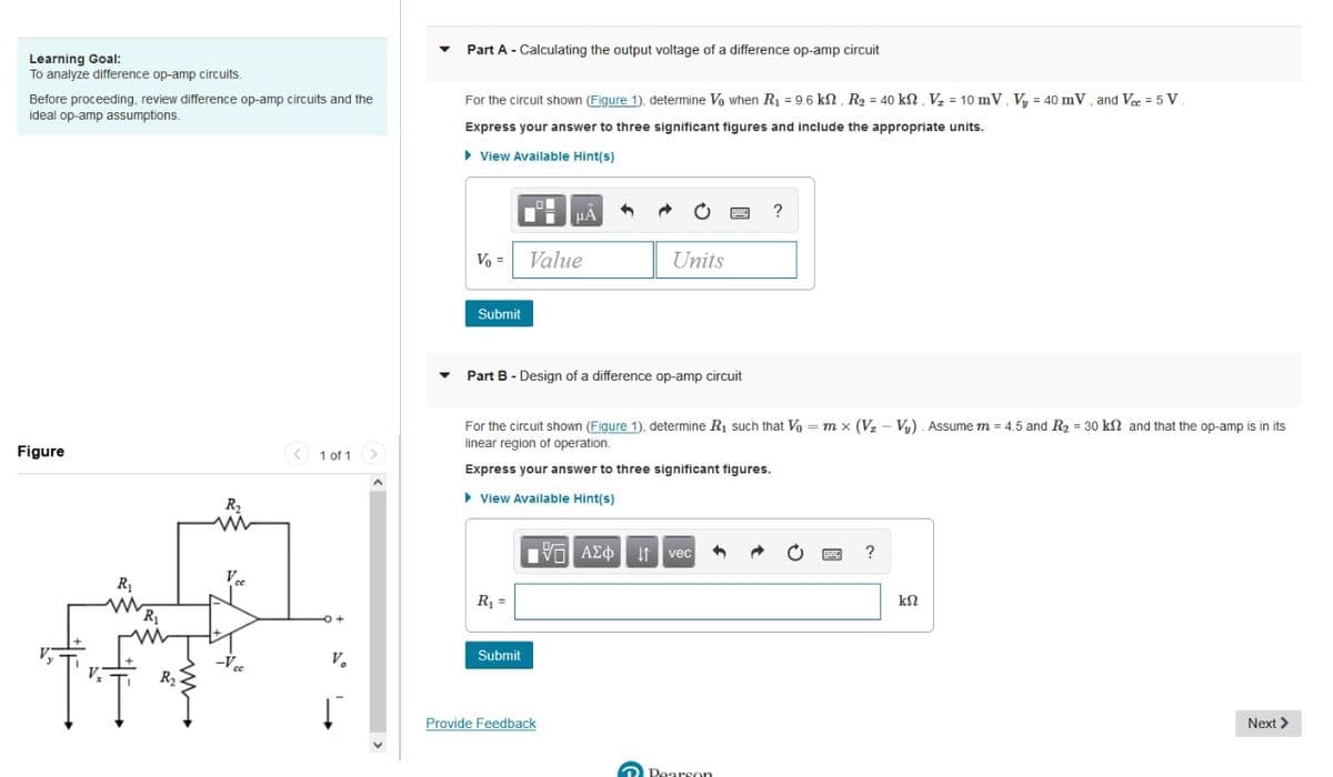
Transcribed Image Text:Part A - Calculating the output voltage of a difference op-amp circuit
Learning Goal:
To analyze difference op-amp circuits.
Before proceeding, review difference op-amp circuits and the
For the circuit shown (Figure 1), determine Vo when R = 9,6 kN. R, = 40 kN. V. = 10 mV. V. = 40 mV. and Ve =5 V
ideal op-amp assumptions.
Express your answer to three significant figures and include the appropriate units.
> View Available Hint(s)
HẢ
?
Vo =
Value
Units
Submit
Part B - Design of a difference op-amp circuit
For the circuit shown (Figure 1), determine R1 such that Vo = m x (Vz - Vy) - Assume m = 4.5 and R2 = 30 kn and that the op-amp is in its
linear region of operation.
Figure
< 1 of 1>
Express your answer to three significant figures.
> View Available Hint(s)
R2
Πνα ΑΣφ
It vec
?
R1
R =
-Vcc
V.
Submit
Provide Feedback
Next >
Dearson
Expert Solution
This question has been solved!
Explore an expertly crafted, step-by-step solution for a thorough understanding of key concepts.

This is a popular solution!

Trending now
This is a popular solution!

Step by step
Solved in 3 steps with 3 images

Knowledge Booster


Learn more about
Need a deep-dive on the concept behind this application? Look no further. Learn more about this topic, electrical-engineering and related others by exploring similar questions and additional content below.Recommended textbooks for you
Delmar's Standard Textbook Of Electricity
Electrical Engineering
ISBN:
9781337900348
Author:
Stephen L. Herman
Publisher:
Cengage Learning
Delmar's Standard Textbook Of Electricity
Electrical Engineering
ISBN:
9781337900348
Author:
Stephen L. Herman
Publisher:
Cengage Learning