2. B. SR Master-Slave Flip-Flop a. Draw the logic diagram of SR master-slave flip-flop and implement it using logic gates. b. Complete the logic simulation below for Y (the output of the master latch) and Q (the output of the slave latch) and show them in your implementation. R
2. B. SR Master-Slave Flip-Flop a. Draw the logic diagram of SR master-slave flip-flop and implement it using logic gates. b. Complete the logic simulation below for Y (the output of the master latch) and Q (the output of the slave latch) and show them in your implementation. R

Chapter22: Sequence Control
Section: Chapter Questions
Problem 6SQ: Draw a symbol for a solid-state logic element AND.

Related questions
Question
I will make the implement part myself.
Hello, Please do what is requested carefully. Logic circuits answers that I usually get from Bartleby are wrong. Please ensure.
I will post the question 2 times.
Can you answer Question b ?
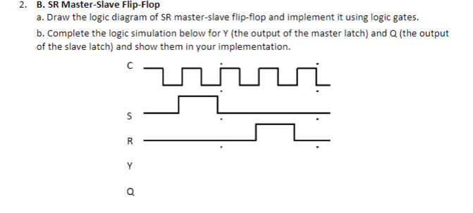
Transcribed Image Text:2. B. SR Master-Slave Flip-Flop
a. Draw the logic diagram of SR master-slave flip-flop and implement it using logic gates.
b. Complete the logic simulation below for Y (the output of the master latch) and Q (the output
of the slave latch) and show them in your implementation.
ninni
R
Q
Expert Solution
This question has been solved!
Explore an expertly crafted, step-by-step solution for a thorough understanding of key concepts.

Step by step
Solved in 3 steps with 2 images

Knowledge Booster


Learn more about
Need a deep-dive on the concept behind this application? Look no further. Learn more about this topic, electrical-engineering and related others by exploring similar questions and additional content below.Recommended textbooks for you