2. Design a combinational logic circuit for 4-input majority circuit. A majority circuit is one which produces a HIGH (1) output when three or more inputs are HIGH (1). Construct the truth table and simplify the Boolean expression into SOP and POS forms using К-mаp. ii. Construct the logic diagram using AND-OR gate network with simplified SOP expression. iii. Construct the logic diagram using OR-AND gate network with simplified POS expression. iv. Construct the logic diagram using only NAND gates with simplified SOP expression. Construct the logic diagram using only NOR gates with simplified POS expression. i. V.
2. Design a combinational logic circuit for 4-input majority circuit. A majority circuit is one which produces a HIGH (1) output when three or more inputs are HIGH (1). Construct the truth table and simplify the Boolean expression into SOP and POS forms using К-mаp. ii. Construct the logic diagram using AND-OR gate network with simplified SOP expression. iii. Construct the logic diagram using OR-AND gate network with simplified POS expression. iv. Construct the logic diagram using only NAND gates with simplified SOP expression. Construct the logic diagram using only NOR gates with simplified POS expression. i. V.

Chapter22: Sequence Control
Section: Chapter Questions
Problem 6SQ: Draw a symbol for a solid-state logic element AND.

Related questions

Question
for question iv and v
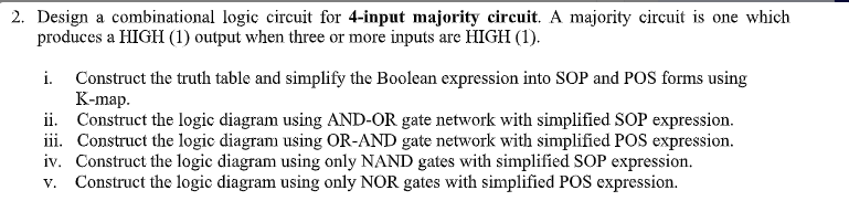
Transcribed Image Text:2. Design a combinational logic circuit for 4-input majority circuit. A majority circuit is one which
produces a HIGH (1) output when three or more inputs are HIGH (1).
Construct the truth table and simplify the Boolean expression into SOP and POS forms using
К-mаp.
ii. Construct the logic diagram using AND-OR gate network with simplified SOP expression.
iii. Construct the logic diagram using OR-AND gate network with simplified POS expression.
iv. Construct the logic diagram using only NAND gates with simplified SOP expression.
Construct the logic diagram using only NOR gates with simplified POS expression.
i.
V.
Expert Solution
This question has been solved!
Explore an expertly crafted, step-by-step solution for a thorough understanding of key concepts.

Step by step
Solved in 3 steps with 3 images

Knowledge Booster


Learn more about
Need a deep-dive on the concept behind this application? Look no further. Learn more about this topic, electrical-engineering and related others by exploring similar questions and additional content below.Recommended textbooks for you