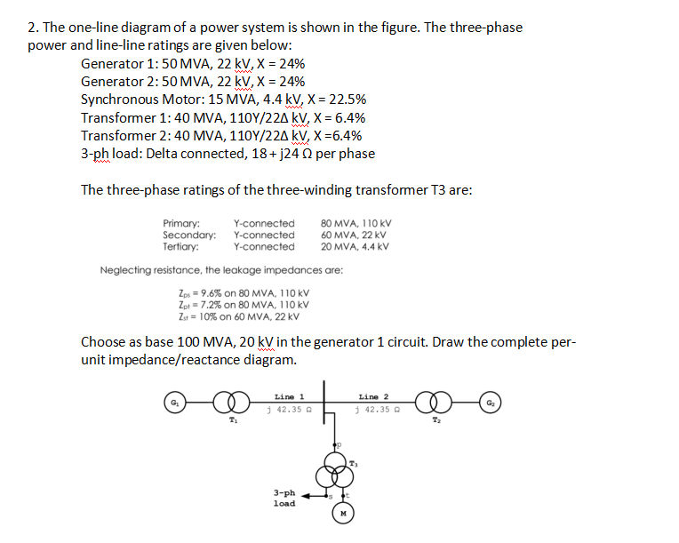
2. The one-line diagram of a power system is shown in the figure. The three-phase power and line-line ratings are given below: Generator 1: 50 MVA, 22 kV, X = 24% Generator 2: 50 MVA, 22 kV, X = 24% Synchronous Motor: 15 MVA, 4.4 kV, X = 22.5% Transformer 1: 40 MVA, 110Y/22A kV, X = 6.4% Transformer 2: 40 MVA, 110Y/22A kV, X =6.4% 3-ph load: Delta connected, 18+ j24 0 per phase www ww The three-phase ratings of the three-winding transformer T3 are: Primary: Secondary: Y-connected Tertiary: 80 MVA, 110 kV 60 MVA, 22 kV 20 MVA, 4.4 kV Y-connected Y-connected Neglecting resistance, the leakage impedances are: Zp, = 9.6% on 80 MVA, 110 kV Zpi = 7.2% on 80 MVA, 110 kV Zu = 10% on 60 MVA, 22 kV Choose as base 100 MVA, 20 kV in the generator 1 circuit. Draw the complete per- unit impedance/reactance diagram.
2. The one-line diagram of a power system is shown in the figure. The three-phase power and line-line ratings are given below: Generator 1: 50 MVA, 22 kV, X = 24% Generator 2: 50 MVA, 22 kV, X = 24% Synchronous Motor: 15 MVA, 4.4 kV, X = 22.5% Transformer 1: 40 MVA, 110Y/22A kV, X = 6.4% Transformer 2: 40 MVA, 110Y/22A kV, X =6.4% 3-ph load: Delta connected, 18+ j24 0 per phase www ww The three-phase ratings of the three-winding transformer T3 are: Primary: Secondary: Y-connected Tertiary: 80 MVA, 110 kV 60 MVA, 22 kV 20 MVA, 4.4 kV Y-connected Y-connected Neglecting resistance, the leakage impedances are: Zp, = 9.6% on 80 MVA, 110 kV Zpi = 7.2% on 80 MVA, 110 kV Zu = 10% on 60 MVA, 22 kV Choose as base 100 MVA, 20 kV in the generator 1 circuit. Draw the complete per- unit impedance/reactance diagram.

Power System Analysis and Design (MindTap Course List)
6th Edition
ISBN:9781305632134
Author:J. Duncan Glover, Thomas Overbye, Mulukutla S. Sarma
Publisher:J. Duncan Glover, Thomas Overbye, Mulukutla S. Sarma
Chapter3: Power Transformers
Section: Chapter Questions
Problem 3.41P: Consider the single-line diagram of the power system shown in Figure 3.38. Equipment ratings are...

Related questions
Question
Transcribed Image Text:2. The one-line diagram of a power system is shown in the figure. The three-phase
power and line-line ratings are given below:
Generator 1:50 MVA, 22 kV, X = 24%
Generator 2:50 MVA, 22 kV, X = 24%
Synchronous Motor: 15 MVA, 4.4 kV, X = 22.5%
Transformer 1:40 MVA, 110Y/22A kV, X = 6.4%
Transformer 2:40 MVA, 110Y/22A kV, X=6.4%
3-ph load: Delta connected, 18+ j24 0 per phase
ww
ww.
The three-phase ratings of the three-winding transformer T3 are:
Primary:
Secondary:
Tertiary:
Y-connected
Y-connected
Y-connected
80 MVA, 110 kV
60 MVA, 22 kV
20 MVA, 4.4 kV
Neglecting resistance, the leakage impedances are:
Zps = 9.6% on 80 MVA, 110 kV
Zpi = 7.2% on 80 MVA, 110 kV
Z = 10% on 60 MVA, 22 kV
Choose as base 100 MVA, 20 kV in the generator 1 circuit. Draw the complete per-
unit impedance/reactance diagram.
Line 1
Line 2
G2
i 42.35 a
j 42.35 a
T2
3-ph
load
Expert Solution
This question has been solved!
Explore an expertly crafted, step-by-step solution for a thorough understanding of key concepts.

Step by step
Solved in 7 steps with 7 images

Recommended textbooks for you
Power System Analysis and Design (MindTap Course …
Electrical Engineering
ISBN:
9781305632134
Author:
J. Duncan Glover, Thomas Overbye, Mulukutla S. Sarma
Publisher:
Cengage Learning

Delmar's Standard Textbook Of Electricity
Electrical Engineering
ISBN:
9781337900348
Author:
Stephen L. Herman
Publisher:
Cengage Learning
Power System Analysis and Design (MindTap Course …
Electrical Engineering
ISBN:
9781305632134
Author:
J. Duncan Glover, Thomas Overbye, Mulukutla S. Sarma
Publisher:
Cengage Learning
Delmar's Standard Textbook Of Electricity
Electrical Engineering
ISBN:
9781337900348
Author:
Stephen L. Herman
Publisher:
Cengage Learning