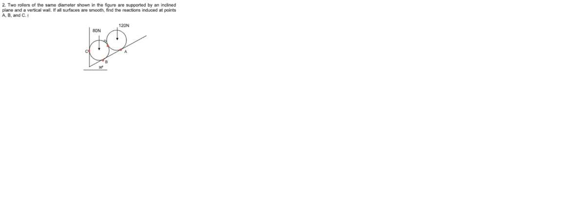
2. Two rollers of the same diameter shown in the figure are supported by an inclined plane and a vertical wall. If all surfaces are smooth, find the reactions induced at points A, B, and C. ( 120N 80N B 30


Q: A frame of two members (AC) and (BD) are connected together at pin B. The other ends are…
A: Using the equilibrium equation tanθ=0.40.3θ=53.13° ∑Fx=0RAH+RDH=500 ....(1)∑Fy=0RAV+RDV=0…
Q: A frame of two members (AC) and (BD) are connected together at pin B. The other ends are pin-…
A: According to the information we have a frame with two members AC and BD that is pinned together at…
Q: Determine the reactions at point O, in the below figure. 210 N F = 500 N 0.125 m 0.3m- 60 0.25 m F=…
A:
Q: Two rollers of the same diameter shown in the figure are supported by an inclined plane and a…
A: Draw the free body diagram of roller 2.
Q: A bracket is subjected to the force-couple system shown in the figure below. Determine the reactions…
A:
Q: 12. 3 B. A. 6, 18 m
A:
Q: Q.14. A mass of 35kg is suspended from a weightless bar AB which is supported by a cable CB and a…
A: The free-body diagram of the system is given as,
Q: y W (N/m) В 5 m 10 m 12 m A beam of length 12 m is in equilibrium, the force is distributed 540 in…
A: Given Data L=12 m w=540 N/m
Q: 3 The ratio of the reactions RA and RB of a simply supported beam shown in * below figure is 5 kN…
A:
Q: Anchor point of the beam given in the figure is fixed support and B point is movable support. Find…
A:
Q: A bracket is subjected to the force-couple system shown in the figure below. Determine the reactions…
A: The free body diagram of the system is as follows:
Q: 2니3 니3
A:
Q: Determine the moment reaction at point A in the clockwise direction in N.m? Set P =411 N, Y =197 mm,…
A: Given data, Load, P=411 N Y = 197 mm = 0.197 m X = 420 mm = 0.42 m To determine, the moment at A in…
Q: Q.2] Find the reactions at point A for the structure shown in the figure. A 10m z kN/m 5m 20 KN #
A: To find; The reaction force at A. Free body diagram: The free body diagram of the structure is shown…
Q: SITUATION 2 A riveted bracket show in the figure is subjected to load P acting at an angle of e from…
A:
Q: If the beam in the figure below is in equilibrium (A is a pin and B is a roller), determine the…
A:
Q: Answer the attached file
A: The free-body diagram of the upper roller can be drawn as below, Here RA and RD are reaction at…
Q: A frame of two members (AC) and (BD) are connected together at pin B. The other ends are…
A: Take moment about the point D Force acting in the x direction is Force acting in the y direction…
Q: The second moment of area about the neutral axis of the H-section shown in the figure is,
A: Given that: The shape is H shape. It is required to determine the second moment of area of the given…
Q: The steel box wrench (E-29,000ksi, v=0.32) loaded with a 40-lb horizontal force and a 25-lb vertical…
A: Note: Since you have posted a question with multiple sub-parts, we will solve first three sub- parts…
Q: The truss is subjected to a mass of 400 kg as shown in the following figure. The truss is supported…
A: Given data The truss is subjected to a mass of 400 kg The truss is supported by a pin at A and a…
Q: Using the figure below, find (a) the reaction forces at B & C, and (b) the forces in the members AB,…
A: The truss is to be analysed for reactions at supports and for member forces . All the forces are…
Q: Clarification: the smooth plane surface at points A and B is inclined at 30 degrees from the…
A: Given data asper question Mass of roller 1 =120 N Mass of roller 2=80 N considering roller…
Q: 23: Triangular plate ABC is connected by means of pin at C with another triangular plate CDE as…
A: According to the details provided in the question, we need to calculate vertical reaction at point…
Q: 1-For the figure below take M number of you and find the reactions? 2-ls the body balanced or not? 3…
A:
Q: For the concentrated load shown in * :the figure. find the reaction RB 50 kN A B 10 m the figure.…
A:
Q: L
A:
Q: The rigid beam ACE is fixed at A as shown in figure, if F1 = 300 kN and F2 = 150 kN. Find the…
A:
Q: 4. (a) Determine the reactions at supports A and E and the maximum tension in the cable in Figure.…
A: In a cable carrying a distributed load cable hangs in a shape of curve internal force is tension…
Q: Body (A) as shown in Figure below has weight equal to(175 N) and the homogenous bar (E ) has weight…
A:
Q: A 11 kN sphere is resting in a trough as shown in Figure. Determine the reactions developed at…
A:
Q: A beam AB is 14 m long weighs 15 N resting on the two supports at the end. If the beam carries loads…
A:
Q: Q.3] Find the reactions at A and B for the structure shown in the figure. 2 kN/m fo lem 2m 20kN 2m…
A: To find: The reaction at A and B . Free body diagram: The free body diagram shown below. Here , RA…
Q: C3/(a) For the figure below take M number of you and find the reactions ? * + 3m 3 m 3 m 12 M- 52. 5…
A:
Q: If the connection at joint C of the frame in figure below is rigid (fixed) *:connection, then the…
A:
Q: A bag of cement weighing 475 N hangs in equilibrium from three wires es suggested in the figure…
A:
Q: Q1: For structure shown in Figure, Find the reactions of the hinge force at A, B, and C. 2 m 200 N/m…
A:
Q: A 6m long beam whose weight is 700 newtons supports a load of 1000 newtons which forms an angle of…
A:
Q: Equilibrium 4-84. Determine the reactions at A and C for the beams shown in Figure P4-84. .6 m A B 8…
A: To determine the reactions at A and C.
Q: vertical mast AE is supported in a ball and socket joint at A and by cables CE and BD as shown in…
A:
Q: 1. For the structure loaded as shown in the figure, find the reactions at A and D.
A: Given data Given force system
Q: C3/(a) For the figure below take M number of you and find the * ? reactions 3 m - 3 m m E C 12 M--…
A:
Q: Q) The member shown in Figure below is pin connected at A and rests against a smooth support at B.…
A: ∵ΣMA=0 →NB x 0.75 = 60 x 1 →NB= 80N
Q: Consider the bracket shown in Fig-3. If: • F1 = 10 lb @ -90° • a = 2 ft • b = 4 ft • c= 1 ft then,…
A:
Q: Q) The member shown in Figure below is pin connected at A and rests against a smooth support at B.…
A: For the given member To determine Pin reaction at A
Q: The 100-cm long shaft CD is subjected to the loading shown in Fig. 4, supported by a journal bearing…
A:
Q: O 4,E 2 P L Problem: Determine the support reaction forces at the two ends of the bar shown above,…
A: Given data as pr question P=6.0×10⁴ NE=2.0×10⁴ Nmm2A=250 mm2L=150 mmΔ=1.2 mm ConsideringFEM Let…
Q: QUESTION 4 For the loaded structural beam shown in the Figure, the resultant support reaction at B…
A:
Q: A frame of two members (AC) and (BD) are connected together at pin 8. The other ends are…
A: Free Body Diagram
Two rollers of the same diameter

Step by step
Solved in 3 steps with 2 images


- The L-shaped arm ABCD shown in the figure lies in a vertical plane and pivots about a horizontal pin at A. The arm has a constant cross-sectional area and total weight W. A vertical spring of stiffness k supports the arm at point B. (a) Obtain a formula for the elongation of the spring due to the weight of the arm. (b) Repeat part (a) if the pin support at A is moved to D.An L-shaped reinforced concrete slab 12 Ft X 12 ft, with a 6 Ft X 6 ft cut-out and thickness t = 9.0 in, is lifted by three cables attached at O, B, and D, as shown in the figure. The cables are are combined at point Q, which is 7.0 Ft above the top of the slab and directly above the center of mass at C. Each cable has an effective cross-sectional area of Ae= 0.12 in2. (a) Find the tensile force Tr(i = 1, 2, 3) in each cable due to the weight W of the concrete slab (ignore weight of cables). (b) Find the average stress ov in each cable. (See Table I-1 in Appendix I for the weight density of reinforced concrete.) (c) Add cable AQ so that OQA is one continuous cable, with each segment having Force T, which is connected to cables BQ and DQ at point Q. Repeat parts (a) and (b). Hini: There are now three Forced equilibrium equations and one constrain equation, T1= T4.The fixed-end bar ABCD consists of three prismatic segments, as shown in the figure. The end segments have a cross-sectional area A1= 840 mm2and length Lt= 200 mm. The middle segment has a cross-sectional area A2= 1260 mm2 and length L2= 250 mm. Loads PBand Pcare equal to 25.5 kN and 17.0 kN, respectively. (a) Determine the reactions RAand RDat the fixed supports. (b) Determine the compressive axial force FBCin the middle segment of the bar.
- Find support reactions at 4 and Band then use the method of joints to find all member forces. Let b = 3 m and P = 80 kN.A circular bar ACB of a diameter d having a cylindrical hole of length .r and diameter till from A to C is held between rigid supports at A and B. A load P acts at U2from ends A and B. Assume E is constant. (a) Obtain formulas for the reactions R, and RBat supports A and B. respectively, due to the load P (see figure part a). (b) Obtain a formula for the displacement S at the point of load application (see figure part a). (c) For what value of x is RB= (6/5)?,? (See figure part a.) (d) Repeat part (a) if the bar is now rotated to a vertical position, load P is removed, and the bar is hanging under its own weight (assume mass density = p). (See figure part b.) Assume that x = LI2.A lube structure is acted on by loads at B and D, as shown in the figure. The tubes are joined using two flange plates at C that are boiled together using six 0.5-in. diameter bolts. (a) Derive formulas for the reactions RAand REat the ends of the bar. (b) Determine the axial displacements S£. Sc, and SDat points B, C. and D. respectively. (c) Draw an axial-displacement diagram (ADD) in which the abscissa is the distance x From support A to any point on the bar and the ordinate is the horizontal displacement Sat that point. (d) Find the maximum value of the load variable P if allowable normal stress in the bolts is 14 ksi.
- By what distance h does the cage shown in the figure move downward when the weight W is placed inside it? (See the figure.) Consider only the effects of the stretching of the cable, which has axial rigidity EA = 10,700 kN. The pulley at A has a diameter da= 300 mm and the pulley at B has a diameter dB= 150 mm. Also, the distance L1= 4.6 m, the distance L2=10.5 m, and the weight W = 22 kN. Note: When calculating the length of the cable. include the parts of the cable that go around the pulley sat A and B.A crane boom of mass 450 leg with its center of mass at C is stabilized by two cables AQ and BQ (Ae= 304 mm2 for each cable) as shown in the figure. A load P = 20 KN is supported at point D. The crane boom lies in the y-z plane. (a) Find the tension forces in each cable: TAQand TBQ(kN}. Neglect the mass of the cables, but include the mass of the boom in addition to load P. (b) Find the average stress (s) in each cable.Space Frame ABC is clamped at A, except it is free to rotate at A about the x and y axes. Cables DC and EC support the frame at C. Force Py= - 50 lb is applied at the mid-span of AS, and a concentrated moment Mx= -20 in-lb acts at joint B. (a) Find reactions at support A. (b) Find cable tension Forces.
- A bar ABC revolves in a horizontal plane about a vertical axis at the midpoint C (see figure). The bar, which has a length 2L and crass-sectional area A, revolves at constant angular speed at. Each half of the bar (AC and BC) has a weight W, and supports a weight W2at its end. Derive the following formula for the elongation of one-half of the bar (that is. the elongation of either AC ar BC). =L223gEA(w1+3w2) in which E is t he modulus of elasticity of the material of the bar and g is the acceleration of gravity.Space frame A BCD is clamped at A, except it is Free to translate in the .v direction. There is also a roller support at D, which is normal to line CDE. A triangularly distributed Force with peak intensity q0 = 75 N/m acts along AB in the positive - direction. Forces Px= 60 N and Pz = = 45 N are applied at joint C, and a concentrated moment My = 120 N . m acts at the mid-span of member BC. (a) Find reactions at supports A and I). (b) Find internal stress resultants N. E’I T, and .11 at the mid-height of segment AB.A uniform bar AB of weight W = 25 N is supported by two springs, as shown in the figure. The spring on the left has a stiffness k[= 300 N/m and natural length Lt=250 mm. The corresponding quantities for the spring on the right are k2= 400 N/m and L^ = 200 mm. The distance between the springs is L = 350 mm, and the spring on the right is suspended from a support that is a distance it = SO mm below the point of support for the spring on the left. Neglect the weight of the springs. (a) At what distance x from the left-hand spring (figure part a) should a load P = 18 N be placed in order to bring the bar to a horizontal position? (b) If P is now removed, what new value of k{is required so that the bar (figure part a) will hang in a horizontal position underweight If? (c) If P is removed and kt= 300 N/m. what distance b should spring ktbe moved to the right so that the bar (figure part a) will hang in a horizontal position under weight II"? (d) If the spring on the left is now replaced by two springs in series (kt= 300 N/m, kt) with overall natural length Lt= 250 mm (see figure part b). what value of k; is required so that the bar will hang in a horizontal position under weight IF?