
Introductory Circuit Analysis (13th Edition)
13th Edition
ISBN: 9780133923605
Author: Robert L. Boylestad
Publisher: PEARSON
expand_more
expand_more
format_list_bulleted
Related questions
Question
3- Design a counter with a control input. When the input is high, the counter should sequence through three states: 10, 01, 11 and repeat. When the input is low the counter should sequence through the same states in the opposite order 11, 01, 10 and repeat.
a) Draw the state diagram and state transition table.
b) Implement the counter using D flip-flops and gates.
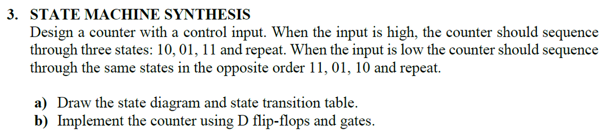

Transcribed Image Text:3. STATE MACHINE SYNTHESIS
Design a counter with a control input. When the input is high, the counter should sequence
through three states: 10, 01, 11 and repeat. When the input is low the counter should sequence
through the same states in the opposite order 11, 01, 10 and repeat.
a) Draw the state diagram and state transition table.
b) Implement the counter using D flip-flops and gates.
Expert Solution
This question has been solved!
Explore an expertly crafted, step-by-step solution for a thorough understanding of key concepts.

This is a popular solution

Trending nowThis is a popular solution!

Step by stepSolved in 3 steps with 3 images

Knowledge Booster


Learn more about
Need a deep-dive on the concept behind this application? Look no further. Learn more about this topic, electrical-engineering and related others by exploring similar questions and additional content below.Similar questions
- 16. The following serial data are applied to the flip-flop through the AND gates as indicated in Figure 7-85 Ⓒ. Determine the resulting serial data that appear on the Qoutput. There is one clock pulse for each bit time. Assume that Q is initially 0 and that and PRE are HIGH. Rightmost bits are applied first. J₁: 1010011; J₂:0111010; J: 1111000; K: 0001110; K 1101100, K: 1010101 CLK K₁ CLR Figure 7-85 C K PRE -Q CLRarrow_forwardSolve for the steady-state value of Vc in Volts (V) for the circuit shown below, assuming that the circuit has been connected for a long time. 5 kN 2 mH 4 mA vC 15V 1 µFarrow_forwardRequired information A fan is to run only when all of the following conditions are met: • Input A is OFF. • Input B is ON or input C is ON, or both B and Care ON. Inputs D and E are both ON. . One or more of inputs F, G, or H are ON. Note: This is a multi-part question. Once an answer is submitted, you will be unable to return to this part. Identify the correct gate logic diagram for the given control system. Multiple Choice Karrow_forward
- Design a\ Up Down Counter that counts from 0 to 7 up and 7 to 0 down by using JK flip flop and verify the output of your designed circuit on any random input. Provide the following information as well:1. State table2. State diagram3. State equations4. Complete circuit diagramarrow_forwardshow the waveforms for each flip-flop output with respect For the ring counter in Figure to the clock. Assume that FF0 is initially SET and that the rest are RESET. Show at least ten clock pulses. D D. FFO FF1 FF2 FF3 FF4 FF5 FF6 FF7 FF8 FP9 CLKarrow_forward3. Consider the counter shown in Figure 2, where the flip-flops are initially set to 0. (a) Determine the logic equations for the J and K inputs of each flip-flop (b) complete the timing diagram (c) construct the state diagram of the counter; (d) deduce the counter modulo. Q1 Q Qo Q J Q Q2 1-K K CLR 1K Q Q CLR CLR CK СК Q2arrow_forward
- Write the next-state equations for the flip-flops and the output equation. (b) Construct the transition and output tables. (c) Construct the transition graph. (d) Give a one-sentence description of when the circuit produces an output of 1. Q2 D2 Q1 T1 CLK Figure 4arrow_forwardThe following statements describe the sequential circuits. Select all the TRUE statements. a The sequential circuits consist of a combinational circuit and storage elements. b The storage elements keep a binary bit even though the circuit power is gone. c Only the current input determines the outputs of sequential logic circuits. d The flip-flop is controlled by signal levels.arrow_forwardasynchronous counters differs from a synchronous counter in * (a) the number of state in sequence (b) the method of clocking (c) the type of flip-flops used (d) the value of the modulusarrow_forward
- 5. JK flip-flops are often used to build counters. The JK flip-flop will toggle the original output value when triggered by the clock signal if both the J,K inputs are connected with a constant "high"(logic 1). All the JK flip-flops in Figure 2 are negative edge triggered. All the initial values of Q2Q1Q0 are 0. Qo (LSB) (MSB) Input K K Logic 1 Input Q2 000 Figure 2. Counter (a) Sketch the output waveforms forQ2 Q1 Q0. Write down the output binary value (Q2Q1Q0: such as "000", "001") for each clock period on the figure. (b) Describe the function of the counter (e.g. binary down counter counting from 7 to 0).arrow_forwardDraw a Moore-type state diagram and design a synchronous sequential circuit using D flip flops for a 1-input/1-output "sequence detector" for the sequence 11 (be sure to recognize overlapping sequences). Draw the final circuit. Draw a Moore-type state diagram and design a synchronous sequential circuit using D flip flops for a 1-input/1-output "sequence detector" for the sequence 100 (be sure to recognize overlapping sequences). Draw the final circuit. Draw a Moore-type state diagram and design a synchronous sequential circuit using D flip flops for a 1-input/1-output "sequence detector" for the sequence 110 (be sure to recognize overlapping sequences). Draw the final circuit. Draw a Moore-type state diagram and design a synchronous sequential circuit using D flip flops for a 1-input/1-output "sequence detector" for the sequence 000 (be sure to recognize overlapping sequences). Draw the final circuit. Draw a Moore-type state diagram and design a synchronous sequential circuit using D…arrow_forwardDesign an Octal Counter with D flip-flops. a) Draw the state diagram b) Draw the state table c) Draw the counter circuitarrow_forward
arrow_back_ios
arrow_forward_ios
Recommended textbooks for you
- Introductory Circuit Analysis (13th Edition)Electrical EngineeringISBN:9780133923605Author:Robert L. BoylestadPublisher:PEARSON
 Delmar's Standard Textbook Of ElectricityElectrical EngineeringISBN:9781337900348Author:Stephen L. HermanPublisher:Cengage Learning
 Programmable Logic ControllersElectrical EngineeringISBN:9780073373843Author:Frank D. PetruzellaPublisher:McGraw-Hill Education
  Fundamentals of Electric CircuitsElectrical EngineeringISBN:9780078028229Author:Charles K Alexander, Matthew SadikuPublisher:McGraw-Hill Education
 Electric Circuits. (11th Edition)Electrical EngineeringISBN:9780134746968Author:James W. Nilsson, Susan RiedelPublisher:PEARSON
 Engineering ElectromagneticsElectrical EngineeringISBN:9780078028151Author:Hayt, William H. (william Hart), Jr, BUCK, John A.Publisher:Mcgraw-hill Education,
Introductory Circuit Analysis (13th Edition)
Electrical Engineering
ISBN:9780133923605
Author:Robert L. Boylestad
Publisher:PEARSON
Delmar's Standard Textbook Of Electricity
Electrical Engineering
ISBN:9781337900348
Author:Stephen L. Herman
Publisher:Cengage Learning
Programmable Logic Controllers
Electrical Engineering
ISBN:9780073373843
Author:Frank D. Petruzella
Publisher:McGraw-Hill Education
Fundamentals of Electric Circuits
Electrical Engineering
ISBN:9780078028229
Author:Charles K Alexander, Matthew Sadiku
Publisher:McGraw-Hill Education
Electric Circuits. (11th Edition)
Electrical Engineering
ISBN:9780134746968
Author:James W. Nilsson, Susan Riedel
Publisher:PEARSON
Engineering Electromagnetics
Electrical Engineering
ISBN:9780078028151
Author:Hayt, William H. (william Hart), Jr, BUCK, John A.
Publisher:Mcgraw-hill Education,