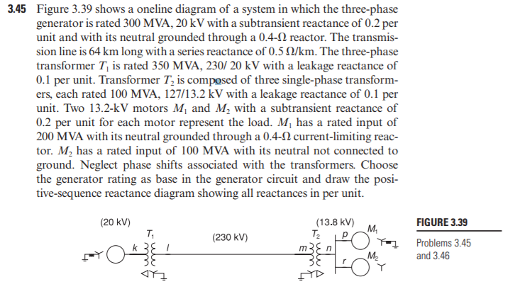
3.45 Figure 3.39 shows a oneline diagram of a system in which the three-phase generator is rated 300 MVA, 20 kV with a subtransient reactance of 0.2 per unit and with its neutral grounded through a 0.4-N reactor. The transmis- sion line is 64 km long with a series reactance of 0.5 N/km. The three-phase transformer T, is rated 350 MVA, 230/ 20 kV with a leakage reactance of 0.1 per unit. Transformer T, is composed of three single-phase transform- ers, each rated 100 MVA, 127/13.2 kV with a leakage reactance of 0.1 per unit. Two 13.2-kV motors M, and M, with a subtransient reactance of 0.2 per unit for each motor represent the load. M, has a rated input of 200 MVA with its neutral grounded through a 0.4-N current-limiting reac- tor. M, has a rated input of 100 MVA with its neutral not connected to ground. Neglect phase shifts associated with the transformers. Choose the generator rating as base in the generator circuit and draw the posi- tive-sequence reactance diagram showing all reactances in per unit. (20 kV) (13.8 kV) Tz FIGURE 3.39 M, (230 kV) Problems 3.45 m3E n 38 M2 and 3.46
3.45 Figure 3.39 shows a oneline diagram of a system in which the three-phase generator is rated 300 MVA, 20 kV with a subtransient reactance of 0.2 per unit and with its neutral grounded through a 0.4-N reactor. The transmis- sion line is 64 km long with a series reactance of 0.5 N/km. The three-phase transformer T, is rated 350 MVA, 230/ 20 kV with a leakage reactance of 0.1 per unit. Transformer T, is composed of three single-phase transform- ers, each rated 100 MVA, 127/13.2 kV with a leakage reactance of 0.1 per unit. Two 13.2-kV motors M, and M, with a subtransient reactance of 0.2 per unit for each motor represent the load. M, has a rated input of 200 MVA with its neutral grounded through a 0.4-N current-limiting reac- tor. M, has a rated input of 100 MVA with its neutral not connected to ground. Neglect phase shifts associated with the transformers. Choose the generator rating as base in the generator circuit and draw the posi- tive-sequence reactance diagram showing all reactances in per unit. (20 kV) (13.8 kV) Tz FIGURE 3.39 M, (230 kV) Problems 3.45 m3E n 38 M2 and 3.46

Power System Analysis and Design (MindTap Course List)
6th Edition
ISBN:9781305632134
Author:J. Duncan Glover, Thomas Overbye, Mulukutla S. Sarma
Publisher:J. Duncan Glover, Thomas Overbye, Mulukutla S. Sarma
Chapter3: Power Transformers
Section: Chapter Questions
Problem 3.45P: Figure 3.39 shows a oneline diagram of a system in which the three-phase generator is rated 300 MVA,...

Related questions
Question
Transcribed Image Text:3.45 Figure 3.39 shows a oneline diagram of a system in which the three-phase
generator is rated 300 MVA, 20 kV with a subtransient reactance of 0.2 per
unit and with its neutral grounded through a 0.4-2 reactor. The transmis-
sion line is 64 km long with a series reactance of 0.5 Q/km. The three-phase
transformer T, is rated 350 MVA, 230/ 20 kV with a leakage reactance of
0.1 per unit. Transformer T, is composed of three single-phase transform-
ers, each rated 100 MVA, 127/13.2 kV with a leakage reactance of 0.1 per
unit. Two 13.2-kV motors M, and M, with a subtransient reactance of
0.2 per unit for each motor represent the load. M, has a rated input of
200 MVA with its neutral grounded through a 0.4-N current-limiting reac-
tor. M, has a rated input of 100 MVA with its neutral not connected to
ground. Neglect phase shifts associated with the transformers. Choose
the generator rating as base in the generator circuit and draw the posi-
tive-sequence reactance diagram showing all reactances in per unit.
(20 kV)
T,
(13.8 kV)
FIGURE 3.39
T2
M,
p
(230 kV)
Problems 3.45
k 3E !
m3E n
M2
and 3.46
Expert Solution
This question has been solved!
Explore an expertly crafted, step-by-step solution for a thorough understanding of key concepts.

This is a popular solution!

Trending now
This is a popular solution!

Step by step
Solved in 4 steps with 2 images

Recommended textbooks for you
Power System Analysis and Design (MindTap Course …
Electrical Engineering
ISBN:
9781305632134
Author:
J. Duncan Glover, Thomas Overbye, Mulukutla S. Sarma
Publisher:
Cengage Learning
Power System Analysis and Design (MindTap Course …
Electrical Engineering
ISBN:
9781305632134
Author:
J. Duncan Glover, Thomas Overbye, Mulukutla S. Sarma
Publisher:
Cengage Learning