3.6 Common-Collector Configuration 26. An input voltage of 2 V rms (measured from base to ground) is applied to the circuit of Fig. 3.21. Assuming that the emitter voltage follows the base voltage exactly and that Ve (rms) = 0.1 V, calculate the circuit voltage amplification (A, = Vo/V) and emitter current for Rg = 1 kN.
3.6 Common-Collector Configuration 26. An input voltage of 2 V rms (measured from base to ground) is applied to the circuit of Fig. 3.21. Assuming that the emitter voltage follows the base voltage exactly and that Ve (rms) = 0.1 V, calculate the circuit voltage amplification (A, = Vo/V) and emitter current for Rg = 1 kN.

Introductory Circuit Analysis (13th Edition)
13th Edition
ISBN:9780133923605
Author:Robert L. Boylestad
Publisher:Robert L. Boylestad
Chapter1: Introduction
Section: Chapter Questions
Problem 1P: Visit your local library (at school or home) and describe the extent to which it provides literature...

Related questions

Question
Common-Collector Configuration problem. Answer no. 26 only
Reference: Electronic device and circuit theory 11th edition by Boylestad
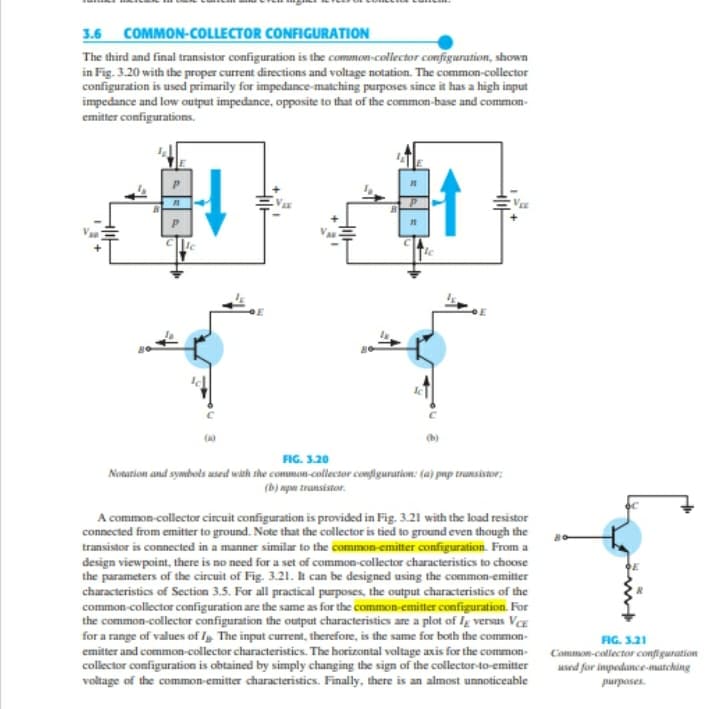
Transcribed Image Text:3.6 COMMON-COLLECTOR CONFIGURATION
The third and final transistor configuration is the common-collector configuration, shown
in Fig. 3.20 with the proper current directions and voltage notation. The common-collector
configuration is used primarily for impedance-matching purposes since it has a high input
impedance and low output impedance, opposite to that of the common-base and common-
emitter configurations.
(b)
FIG. 3.20
Notation and symbots used with the common-collector configuration: (a) pup transistor;
(b) apa transistor.
A common-collector cireuit configuration is provided in Fig. 3.21 with the load resistor
connected from emitter to ground. Note that the collector is tied to ground even though the
transistor is connected in a manner similar to the common emitter configuration. From a
design viewpoint, there is no need for a set of common-collector characteristics to choose
the parameters of the circuit of Fig. 3.21. It can be designed using the common-emitter
characteristics of Section 3.5. For all practical purposes, the output characteristics of the
common-collector configuration are the same as for the common-emitter configuration. For
the common-collector configuration the output characteristics are a plot of Ig versus VCE
for a range of values of I, The input current, therefore, is the same for both the common-
emitter and common-collector characteristics. The horizontal voltage axis for the common-
collector configuration is obtained by simply changing the sign of the collector-to-emitter
voltage of the common-emitter characteristics. Finally, there is an almost unnoticeable
FIG. 3.21
Comon-collector configuration
used for impedance-marching
purposes.
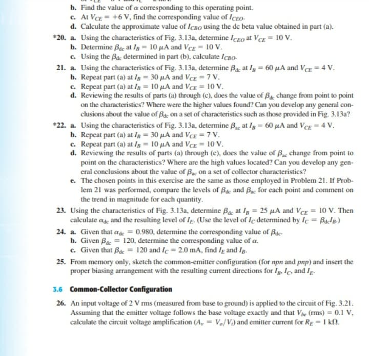
Transcribed Image Text:b. Find the value of a corresponding to this operating point.
c. At VCE = +6 V, find the corresponding value of ICEo-
d. Calculate the approximate value of ICBO using the de beta value obtained in part (a).
*20. a. Using the characteristics of Fig. 3.13a, determine IcEO at VcE = 10 V.
b. Determine Bac at Ig = 10 µA and VcE = 10 V.
c. Using the Bac determined in part (b), calculate IcBo-
21. a. Using the characteristics of Fig. 3.13a, determine Bg, at lg = 60 µA and Vcg = 4 V.
b. Repeat part (a) at Ig = 30 µA and VcE = 7 V.
c. Repeat part (a) at Ig = 10 µA and VcE = 10 V.
d. Reviewing the results of parts (a) through (c), does the value of Bg. change from point to point
on the characteristics? Where were the higher values found? Can you develop any general con-
clusions about the value of Ba: on a set of characteristics such as those provided in Fig. 3.13a?
*22. a. Using the characteristics of Fig. 3.13a, determine Byc at Ig = 60 µA and VcE = 4 V.
b. Repeat part (a) at Ig = 30 µA and VcE =7 V.
c. Repeat part (a) at Ig = 10 µA and VCE = 10 V.
d. Reviewing the results of parts (a) through (c), does the value of Bac change from point to
point on the characteristics? Where are the high values located? Can you develop any gen-
eral conclusions about the value of Bac On a set of collector characteristics?
e. The chosen points in this exercise are the same as those employed in Problem 21. If Prob-
lem 21 was performed, compare the levels of Bac and Bac for each point and comment on
the trend in magnitude for each quantity.
23. Using the characteristics of Fig. 3.13a, determine Ba, at Ig = 25 µA and VcE = 10 V. Then
calculate ag and the resulting level of Ig. (Use the level of Ic determined by Ic = Bap.)
24. a. Given that ase = 0.980, determine the corresponding value of Bac-
b. Given Bac = 120, determine the corresponding value of a.
c. Given that Bác = 120 and Ic = 2.0 mA, find Ig and Ig.
25. From memory only, sketch the common-emitter configuration (for npn and pnp) and insert the
proper biasing arrangement with the resulting current directions for Ig. Ic, and Ig.
3.6 Common-Collector Configuration
26. An input voltage of 2 V rms (measured from base to ground) is applied to the circuit of Fig. 3.21.
Assuming that the emitter voltage follows the base voltage exactly and that Ve (rms) = 0.1 V,
calculate the circuit voltage amplification (A, = V,/V) and emitter current for Rg = 1 kN.
Expert Solution
This question has been solved!
Explore an expertly crafted, step-by-step solution for a thorough understanding of key concepts.

This is a popular solution!

Trending now
This is a popular solution!

Step by step
Solved in 3 steps with 3 images

Knowledge Booster


Learn more about
Need a deep-dive on the concept behind this application? Look no further. Learn more about this topic, electrical-engineering and related others by exploring similar questions and additional content below.Recommended textbooks for you
Introductory Circuit Analysis (13th Edition)
Electrical Engineering
ISBN:
9780133923605
Author:
Robert L. Boylestad
Publisher:
PEARSON

Delmar's Standard Textbook Of Electricity
Electrical Engineering
ISBN:
9781337900348
Author:
Stephen L. Herman
Publisher:
Cengage Learning

Programmable Logic Controllers
Electrical Engineering
ISBN:
9780073373843
Author:
Frank D. Petruzella
Publisher:
McGraw-Hill Education
Introductory Circuit Analysis (13th Edition)
Electrical Engineering
ISBN:
9780133923605
Author:
Robert L. Boylestad
Publisher:
PEARSON
Delmar's Standard Textbook Of Electricity
Electrical Engineering
ISBN:
9781337900348
Author:
Stephen L. Herman
Publisher:
Cengage Learning
Programmable Logic Controllers
Electrical Engineering
ISBN:
9780073373843
Author:
Frank D. Petruzella
Publisher:
McGraw-Hill Education

Fundamentals of Electric Circuits
Electrical Engineering
ISBN:
9780078028229
Author:
Charles K Alexander, Matthew Sadiku
Publisher:
McGraw-Hill Education

Electric Circuits. (11th Edition)
Electrical Engineering
ISBN:
9780134746968
Author:
James W. Nilsson, Susan Riedel
Publisher:
PEARSON

Engineering Electromagnetics
Electrical Engineering
ISBN:
9780078028151
Author:
Hayt, William H. (william Hart), Jr, BUCK, John A.
Publisher:
Mcgraw-hill Education,