
Database System Concepts
7th Edition
ISBN: 9780078022159
Author: Abraham Silberschatz Professor, Henry F. Korth, S. Sudarshan
Publisher: McGraw-Hill Education
expand_more
expand_more
format_list_bulleted
Related questions
Question
thumb_up100%
Need 2 different variations answers and with explanation please. Thank you.
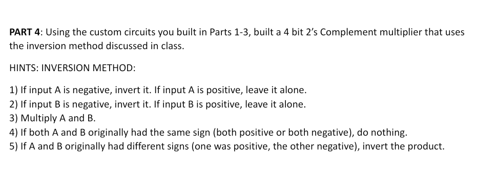

Transcribed Image Text:PART 4: Using the custom circuits you built in Parts 1-3, built a 4 bit 2's Complement multiplier that uses
the inversion method discussed in class.
HINTS: INVERSION METHOD:
1) If input A is negative, invert it. If input A is positive, leave it alone.
2) If input B is negative, invert it. If input B is positive, leave it alone.
3) Multiply A and B.
4) If both A and B originally had the same sign (both positive or both negative), do nothing.
5) If A and B originally had different signs (one was positive, the other negative), invert the product.

Transcribed Image Text:4 bit 2's Complement Multiplier
INPUT A: 4 bit 2's Complement number
INPUT B: 4 bit 2's Complement number
OUTPUT: the product of A x B represented as a 8 bit 2's Complement number
You are only allowed to use the basic gates: NOT, AND, OR, XOR. You may however, use these basic gates
to build your own custom circuits (i.e. Adder). You are NOT ALLOWED to use Logisim built in circuits.
Each custom circuit is to be implemented as a sub-circuit.
PART 1: Build a 4 bit controlled 2's Complement Inverter
PART 2: Build a 8 bit controlled 2's Complement Inverter
PART 3: Build a 4 Bit UNSIGNED Multiplier
A: 4 Bit Input
B: 4 Bit Input
Multiplier
0000 000O
Expert Solution
This question has been solved!
Explore an expertly crafted, step-by-step solution for a thorough understanding of key concepts.

This is a popular solution

Trending nowThis is a popular solution!

Step by stepSolved in 4 steps with 3 images

Knowledge Booster


Learn more about
Need a deep-dive on the concept behind this application? Look no further. Learn more about this topic, computer-science and related others by exploring similar questions and additional content below.Similar questions
arrow_back_ios
arrow_forward_ios
Recommended textbooks for you
- Database System ConceptsComputer ScienceISBN:9780078022159Author:Abraham Silberschatz Professor, Henry F. Korth, S. SudarshanPublisher:McGraw-Hill Education
 Starting Out with Python (4th Edition)Computer ScienceISBN:9780134444321Author:Tony GaddisPublisher:PEARSON
 Digital Fundamentals (11th Edition)Computer ScienceISBN:9780132737968Author:Thomas L. FloydPublisher:PEARSON
  C How to Program (8th Edition)Computer ScienceISBN:9780133976892Author:Paul J. Deitel, Harvey DeitelPublisher:PEARSON
 Database Systems: Design, Implementation, & Manag...Computer ScienceISBN:9781337627900Author:Carlos Coronel, Steven MorrisPublisher:Cengage Learning
 Programmable Logic ControllersComputer ScienceISBN:9780073373843Author:Frank D. PetruzellaPublisher:McGraw-Hill Education
Database System Concepts
Computer Science
ISBN:9780078022159
Author:Abraham Silberschatz Professor, Henry F. Korth, S. Sudarshan
Publisher:McGraw-Hill Education
Starting Out with Python (4th Edition)
Computer Science
ISBN:9780134444321
Author:Tony Gaddis
Publisher:PEARSON
Digital Fundamentals (11th Edition)
Computer Science
ISBN:9780132737968
Author:Thomas L. Floyd
Publisher:PEARSON
C How to Program (8th Edition)
Computer Science
ISBN:9780133976892
Author:Paul J. Deitel, Harvey Deitel
Publisher:PEARSON
Database Systems: Design, Implementation, & Manag...
Computer Science
ISBN:9781337627900
Author:Carlos Coronel, Steven Morris
Publisher:Cengage Learning
Programmable Logic Controllers
Computer Science
ISBN:9780073373843
Author:Frank D. Petruzella
Publisher:McGraw-Hill Education