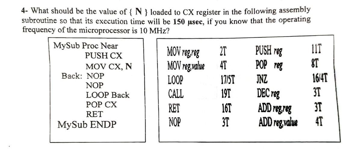
4- What should be the value of { N } loaded to CX register in


Q: What is D Latch? Explain.
A:
Q: 4. The equation for a voltage is given by e = 170.35 sin a. Determine the instantaneous values of…
A:
Q: Q3: For the specify all reactance in.u.. Take S, = 100 MVA, V, = 33 kV M. 40 MVA. x,, - 0.20 pu 30…
A:
Q: Problem 17: The voltage across a 1 µF capacitor is given. What is the sinusoidal expression for the…
A: We need to find out current for given voltage .
Q: 2 A Triac control of a three-phase, 30 kW, 400 V, 50 Hz, six-pole, star- connected squirrel-cage…
A: TRIAC: The full form of Triac is Triode for alternating current. It is also called bidirectional…
Q: A single phase transformer is connected to a 660 V supply . The voltage to turn ratic transformer is…
A: In this question we will find transformers primary and secondary turns and area of core...
Q: QUESTION 29 If R1 = 80, R2 = 300. The source Voltage is 120 Volts. I, VAC R1 R2 I1 12 Find the…
A:
Q: The settling time of an underdamped system is 4 seconds, the time constant is, O a. 16 sec O b. 1…
A: Given data, The settling time of an underdamped system, ts=4 s
Q: Part 3: Resistors in Parallel and Series Aim: To understand how the magnitude of the total…
A: TWO RESISTORS IN SERIES WITH A BATTERY:
Q: 1. Consider the unity feedback system below R(s) + E(s) C(s) G(s) K G(s) (s + 4)³ 2. Find the…
A: Solve first three sub-parts in a multiple sub-part question, unless the student has asked for…
Q: There are two loads connected in parallel and powered from a 7200-V source. The first load is 50-kVA…
A:
Q: 5:1 transformers are connected in Delta-Wye to step up the voltage at the beginning of a 12,300-volt…
A:
Q: Q 6\ for the class -B Power amplifier shown in fig(3), the input voltage is to be Vs = lo sina t ,…
A: According to the question, for the given class B amplifier as shown below
Q: Find the V(t) that satisfies the following differential equation and initial conditions. d?v dV +25V…
A:
Q: need to convert the drawing from a handwritten drawing to a typeface on the computer, please OPEN…
A: Given,
Q: Refer to the circuit in Figure 2. The switch was closed for a long time, analyse the following for…
A:
Q: A three-phase, 7.5Hp, 230V, 60Hz, Delta connected induction motor was tested and give the following…
A: no load power= 650 W at certain load , power=6800 W at 3 % slip Stator resistance is Rs…
Q: Describe the conductivity of a conductor explain its conductivity in terms of the electrons in it
A: Conductivity is the measure of a material's capability to carry current flowing through it. It is…
Q: Q3) (a) If the SNR of a wireless link is 18dB and the RF bandwidth is 30kHz, using Shannon's…
A:
Q: Short Circuit T-L, sketch the SW Pattern for Ed sketch the Variation of Zd with distance ,d%3D0, 8.…
A: Impedance at lambda/4 distance from receiving end is infinite
Q: 5.10 Solve all praghraphs 2.6 Solve all praghraphs 1)The binary number 10101 is equivalent to the…
A: In this question we will find binary to decimal equivalent, force , inductance etc...
Q: Given Vdc =10 V in the circuit below, what is the maximum value of R that can be used for this…
A:
Q: Q3: Explain with aid of figures and equations the type of quantization and the quantization error.…
A: The quantization is a process of converting an analog signal into an equivalent digital signal. This…
Q: Determine the B, value from this polarization curve. -300 -350 -400 -450 -500 -550 -600 -650 -700…
A: A A polarization curve is given in the question. We need to determine the value of βa.
Q: 1. Design an Op Amp Summerto implement the ffequation: Vo = 4v1 + v2- 8v, - 6v,
A:
Q: Example25/ T-L with Zo=600 0,ZR = 100 Q. Find the length and location of the %3D single stub…
A:
Q: I need to convert the drawing from a handwritten drawing to a typeface on the computer, please Vs E
A: Circuit diagram is given as,
Q: What is the voltage Vin the following circuit? + 1V – - + 5 V + 5 A A (V 4Ω. -
A:
Q: An AC voltage of 230 v is applied to a circuit consisting of a resistance of 10 ohms in series with…
A:
Q: *2. Using superposition, determine the current I for each network of Fig. 18.110. R Iz 32 62 E = 10…
A:
Q: (c) If the carrier in part (b) has a peak-to-peak voltage of 12V and the modulating signal has a…
A: We need to find out the voltage for given amplitude modulation .
Q: What is the equivalent resistance between the terminals a and b? 6 N ww 6 N bọ 6 N 2 N 8 N ww ww
A:
Q: Example25/ T-L with Zo=6000, ZR = 100 Q. Find the length and location of the %3D single stub…
A:
Q: 5. Indicate the solid insulation applications in (a) Power Cables (b) HV Bushings (c) Small-size…
A: A) solid insulation applications in power cables: Commonly used insulation materials in cables are…
Q: Design an unregulated power supply consisting of a center-tapped transformer full-wave rectifier and…
A: Unregulated power supplies are used where the load requires constant power with low ripple. A Centre…
Q: Compute the cost per hour at 7.50 pesos per kwh of electrifying the house. If the appliances inside…
A:
Q: a. 20 sin (377t – 180°) b. 6 x 10⁻⁶ cos wt c. 3.6 x 10¬° cos (754t – 20°)
A:
Q: (c)[ The magnetic device of the figure is designed to operate with 240 V(rms) at 50HZ. For operation…
A: This question is related to magnetic circuits
Q: Problem 42: Perform the following subtractions in rectangular form: a. (9.8 + j6.2) – (4.6+ j4.6) b.…
A: We need to find perform addition and subtraction for the given complex number
Q: A single-phase, 250-kVA, 11-kV/415-V, 50-Hz transformer has 80 turns on the secondary. Calculate (a)…
A: The solution is given below
Q: The switch in the circuit of Figure 2 has been closed for a long time but is opened at t= 0 s.…
A:
Q: Design a sequential circuit with two D flip-flops and two input x and y. When x=0, the state remains…
A: The state table is a tabular representation of the behavior of the system for different inputs and…
Q: For a two-port reciprocal network, the three transmission parameters are A = 4, B =7 and C= 5. What…
A: Two Port Reciprocal Network: A two-port network (also known as a quadripole or four-terminal…
Q: The value of current I in the circuit shown below is: 1Ω 2Ω 3Ω I V)5 A 1Ω 2Ω 1Ω
A:
Q: The figure represents the equivalent circuit of a single-phase transformer, if after doing the…
A:
Q: Vs E 7.
A: Made it
Q: In a tansistor, IC = 100 mA and IE = 100.2 mA. The value of B O50 O100 about to1 O 200
A:
Q: Refer to circuit in Figure 3, determine i(t) at t> 0 s. t= 0 10 60 i(t) 1 mF 30 V + 40 2.5 H Figure…
A: The solution is given below
Q: 2700 120mH VL VR 6µF 0.234 sin(3000t – 10°)A
A:
Q: Solve the difference equation xn+2 Xn+1 – 2xn = 0 with xo O and x1 = 1. | Select one: (-1)" O (1)" –…
A:

Step by step
Solved in 2 steps with 1 images


- Draw pinouts of 8088 or 8086 microprocessor (μp). Also draw schematics of 8088/8086 μp buses with Latch(s) [IC: 74LS373] and Buffer(s) [IC: 74LS245]. Write purpose of using latch and buffer ICs with μp buses. Please Answer all parts1. Write down 2- differences between Von-Neumann and Harvard architecture. 2. you are executing an instruction, SUB $s0, $s1, $s2 (address 0x20). Draw the datapath of this instruction when $s1=10, $s2=5. When are the stages in this datapath? Mark the components which are active in corresponding stages. 3. How to store(1050000)10 in register $s0? Write down the instructions that stores the data in $s0 register.Please design a 6:1 multiplexer following the below procedures with data inputs of D5, D4, D3,D2, D1, D0 and output of Y.1 How many select signals are needed for this Mux.2) List a truth table for this Mux. Note: for all the unused combinations of select signals, Y=D53) Develop an optimized function for this Mux.4) Sketch the logic diagram of implementing this 6:1 Mux.5) Write a complete VHDL structural model to implement the above 6:1 multiplexer. Assume allthe required sub-component (standard gates) VHDL models are given/known that you can use
- Behavioural Up Counter With Max Design and implement a 8-bit resetable up count, that stops counting when max is reached. The ports are: module counter( output u8_t count, input u8_t max, input logic clk, reset); The u8_t type is defined in the test bench. count is the counter's output. The counter should increment by one for even positive edge clock until the max is reached. The counter should not increment when max is reached. The counter is reset if reset = 1 when a positive edge clock occurs. The 8-bit comparator module, cmp, must be used to check when max is reached. The test bench will set max to 150 for its testing. Editor // include cmp module module counter( output u8_t count, input u8_t max,input logic clk, reset);logic m_test; cmp test(m_test, count, max); // complete the restendmodule. Flag Register is a special purpose. Name two types of registers used in 8086 microprocessor. Consider the given example and explain how over flow, carry, parity and auxiallry flag will work on these instruction. MOV AL, 50 (50 is 01010000 which is positive) MOV BL, 32 (32 is 00110010 which is positive) DD AL, BL (82 is 10000010 which is negative)What is the hexadecimal value stored in Register A after the following assembler has executed? LDA #0x71 NOTA NOTA LDR B,#0x71 ADC A,B LDR B,#0xEB ADC A,B NOTA LDR B,#0xD5 ADC A,B LDR B,#0x53 SBC A,B LDR B,#0x19 SBC A,B LDR B,#0x5E SBC A,B
- Design a binary multiplier that multiplies two 8-bit binary number by following design rules thatshown in class. The Q and B are the two separate 8-bit binary inputs, C is the 3-bit sequence counterand R is the 16-bit result. (Note: Explain the registers that you will use to establish given process.) The steps are writing algorithm Drawing circuit undetailed (Just use the box, which have only writin under that their functions) Draw logic circuits one by one showing the internal structure of the boxes. Mahe flow chards for registersA 4-bit universal shifting register QA, QB, QC and QD and a single serial input called SI, has two inputs so that they determine how to operate, as follows: M0M1 = 00 indicates that it should keep the value of the current outputs, M0M1 = 01 indicates that you should shift right, M0M1 = 10 indicates that you should shift left, and M0M1 = 11 indicates that you should parallel load inputs A, B, C, and D. Design a minimum circuit that implement this record and draw the final schematic diagram. Include the entire design procedure1:The output of a logic gate is 1 when all the input are at logic 1 and a . OR and EX - NOR Gate b . AND Gate and EX - OR Gate C. OR and EX - OR Gate d . NAND and OR Gate 2: Choose an application of A / D convertor a. Sonar systems b. Radars and Jammers C. Digital Audio apllications d. Encoders 3: Find the simplification of AB + B ( B + C ) + C ( B + C ) a. C + A b. B + C c. 1 d. A + 4: Choose a correct number of input lines for a decoder which has 128 output lines a . 14 b . 7 c . 1 d . 128 6: Select a suitable example for sequential logic circuit . a . Encoder b . None of the given choices c . Counters d . PAL
- Q: State the differences in transfer operation between 8086 & 8088 MP when executing the instruction MOV [1300 H],BXPlease answer these questions for me to understand our lesson better. Thank you!1. Which IC that outputs 1 when both inputs are 1? 2. What is the output of 7432IC if one of the inputs is 1? 3. Which IC outputs 1 if inputs are complemented? 4. What IC is the complement of an OR gate?How to build this circuit? (on Digital or Logisim) Binary-coded decimal is an alternative method of representing integers using binary. In it, each base-10 digit is represented by four bits, thus each nibble takes one of 10 values (0000 through 1001). Therefore, using BCD, 42 (decimal) is represented as 0100 0010 (binary) and 196 (decimal) is represented as 0001 1001 0110 (binary). Create a circuit in Logisim that accepts as input a pair of two-digit integers represented as BCD and outputs their sum in BCD. Any and all Digital components are fair game. You can assume that all inputs will be valid BCD-encoded numbers.