5. Calculate the theoretical minimum value of RL required for putting the zener diode in the zener breakdown region for the regulator circuit of Fig.8. What value of load resistance results in the maximum zener current? Determine the maximum zener current Izimax) in this case and compare it with IzM-
5. Calculate the theoretical minimum value of RL required for putting the zener diode in the zener breakdown region for the regulator circuit of Fig.8. What value of load resistance results in the maximum zener current? Determine the maximum zener current Izimax) in this case and compare it with IzM-

Introductory Circuit Analysis (13th Edition)
13th Edition
ISBN:9780133923605
Author:Robert L. Boylestad
Publisher:Robert L. Boylestad
Chapter1: Introduction
Section: Chapter Questions
Problem 1P: Visit your local library (at school or home) and describe the extent to which it provides literature...

Related questions

Question
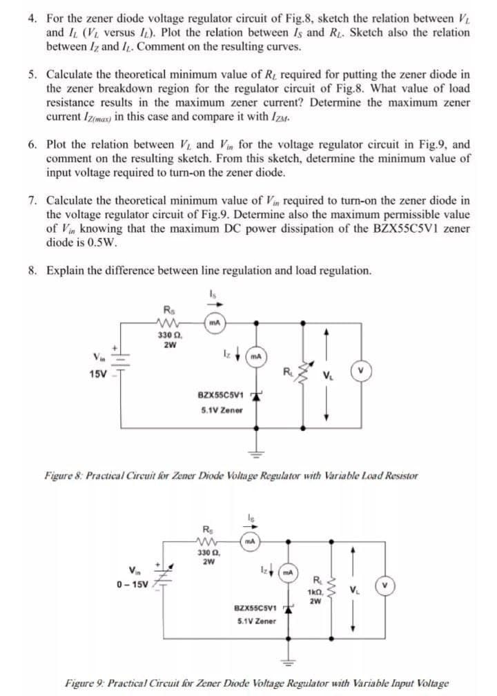
Transcribed Image Text:4. For the zener diode voltage regulator circuit of Fig.8, sketch the relation between V
and IL (VL versus I). Plot the relation between Is and R. Sketch also the relation
between Iz and I. Comment on the resulting curves.
5. Calculate the theoretical minimum value of R required for putting the zener diode in
the zener breakdown region for the regulator circuit of Fig.8. What value of load
resistance results in the maximum zener current? Determine the maximum zener
current Iz(mar) in this case and compare it with IZM.
6. Plot the relation between V and Vin for the voltage regulator circuit in Fig.9, and
comment on the resulting sketch. From this sketch, determine the minimum value of
input voltage required to turn-on the zener diode.
7. Calculate the theoretical minimum value of Vin required to turn-on the zener diode in
the voltage regulator circuit of Fig.9. Determine also the maximum permissible value
of Vin knowing that the maximum DC power dissipation of the BZX55C5V1 zener
diode is 0.5W.
8. Explain the difference between line regulation and load regulation.
Rs
mA
330 0,
2W
V
15V
R
BZX55C5V1
5.1V Zener
Figure 8: Practical Circuit for Zener Diode Voltage Regulator with Variable Load Resistor
mA
330 0,
Va
R
0- 15V
V.
1kn,
2W
BZX55C5V1
5.1V Zener
Figure 9: Practical Circuit for Zener Diode Voltage Regulator with Variable Input Voltage
Expert Solution
This question has been solved!
Explore an expertly crafted, step-by-step solution for a thorough understanding of key concepts.

This is a popular solution!

Trending now
This is a popular solution!

Step by step
Solved in 2 steps with 2 images

Knowledge Booster


Learn more about
Need a deep-dive on the concept behind this application? Look no further. Learn more about this topic, electrical-engineering and related others by exploring similar questions and additional content below.Recommended textbooks for you
Introductory Circuit Analysis (13th Edition)
Electrical Engineering
ISBN:
9780133923605
Author:
Robert L. Boylestad
Publisher:
PEARSON

Delmar's Standard Textbook Of Electricity
Electrical Engineering
ISBN:
9781337900348
Author:
Stephen L. Herman
Publisher:
Cengage Learning

Programmable Logic Controllers
Electrical Engineering
ISBN:
9780073373843
Author:
Frank D. Petruzella
Publisher:
McGraw-Hill Education
Introductory Circuit Analysis (13th Edition)
Electrical Engineering
ISBN:
9780133923605
Author:
Robert L. Boylestad
Publisher:
PEARSON
Delmar's Standard Textbook Of Electricity
Electrical Engineering
ISBN:
9781337900348
Author:
Stephen L. Herman
Publisher:
Cengage Learning
Programmable Logic Controllers
Electrical Engineering
ISBN:
9780073373843
Author:
Frank D. Petruzella
Publisher:
McGraw-Hill Education

Fundamentals of Electric Circuits
Electrical Engineering
ISBN:
9780078028229
Author:
Charles K Alexander, Matthew Sadiku
Publisher:
McGraw-Hill Education

Electric Circuits. (11th Edition)
Electrical Engineering
ISBN:
9780134746968
Author:
James W. Nilsson, Susan Riedel
Publisher:
PEARSON

Engineering Electromagnetics
Electrical Engineering
ISBN:
9780078028151
Author:
Hayt, William H. (william Hart), Jr, BUCK, John A.
Publisher:
Mcgraw-hill Education,