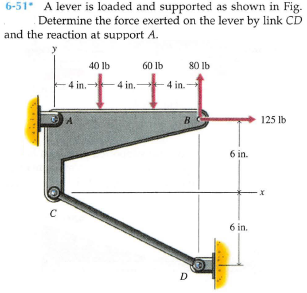
6-51 A lever is loaded and supported as shown in Fig. Determine the force exerted on the lever by link CD and the reaction at support A. 40 lb 60 lb 80 lb 4 in. 4 in.- 4 in. B 125 lb 6 in. 6 in. D
Q: 5-31. Determine the force in members AF, BF, and BC, and state if the members are in tension or…
A: The free body diagram of the truss having forces in member AF, BF, and BC is given below,
Q: 6-53 Determine the force exerted by the cable at B and the reaction at support A of the bar shown in…
A: Drawing the free body diagram of the system, T is the force in cable. Taking the moment about A,
Q: 6-46. Determine the force in members BE, EF, and CB, and state if the members are in tension or…
A:
Q: 6-54 The man shown in Fig. the beam has a mass of 40 kg. The beam is in equilibrium with the man…
A: Draw the free body diagram of the beam.
Q: 5-30. Determine the force in members EF, CF, and BC, and state if the members are in tension or…
A: Draw the free body diagram of the whole structure and calculate the reactions. Apply static…
Q: 4/7 Determine the force in member AC of the loaded truss. The two quarter-circular members act as…
A: Given :- Determine the force in member AC of the loaded truss. The two quarter-circular members act…
Q: 6-23. The Fink truss supports the loads shown. Determine the force in each member and state if the…
A:
Q: Solve for the reactions at roller A and pin G. Solve for the force members: IJ, DJ, DE.
A: GIVEN: TO FIND:
Q: 6-100 Abracket is loaded and supported as shown in Fig. Determine the reactions at supports A and B.…
A: The free body diagram is shown below with the reaction forces acting at A & B . As A is hinge so…
Q: 5-5. Determine the force in each member of the truss and state if the members are in tension or…
A: Given: The magnitude of load, P = 4 kN The free body diagram for the section passing through…
Q: 6-43. Determine the force in members CD, CJ, GJ, and CG and state if these members are in tension or…
A:
Q: The member OBC and sheave at C together have a mass of 500 kg, with a combined center of mass at G.…
A:
Q: 6-5. Determine the force in each member of the truss, and state if the members are in tension or…
A:
Q: 6-52 Determine the reactions at supports A and B of the curved bar shown in Fie. 3 kN 4 kN 0.5 m Im…
A: Draw free body diagram for given beam Taking net moment about B to determine reactions at A
Q: 3-26. The wooden headframe is subjected to the loading shown. Determine the forces in members HI,…
A:
Q: P5-2. Identify the zero-force members in each truss 800 N F3m 3 m 3 m-
A: Consider the free body diagram of the given truss as shown below. From the moment equilibrium about…
Q: The boy at D has a mass of 50 kg, a center of mass at G, and stands on a plank at the position…
A:
Q: 6-45. Determine the force in members BF, BG, and AB, and state if the members are in tension or…
A: Taking the section of truss by cutting member BG, BA, and FG. Taking the upper part to draw the FBD.…
Q: 3/52 To test the deflection of the uniform 100-kg beam the 50-kg boy exerts a pull of 150 N on the…
A:
Q: F6-7. Determine the force in members BC, CF, and FE. State if the members are in tension or…
A:
Q: 6-7. Determine the force in each member of the truss and state if the members are in tension or…
A:
Q: has a mass of 6-84 The block W shown in Fig. 250 kg. Bar AB rests against a smooth vertical wall at…
A: Given Mass of bar m=250kg
Q: QI The planar truss is supported by a pin connection at 4 and a roller at E. Two vertical external…
A:
Q: 6-44 Determine the force exerted by the cable at B and the reaction at support A of the curved bar…
A: Given data as per question Force applied =850 N considering free body diagram of the system in Δ…
Q: *5-28. Determine the force in members EF, BE, BC, and BF of the truss and state if these members are…
A: Given Applied load P1 = 9 kN P2 = 12 kN P3 = 6 kN To find Forces FEF FBE FBC FBF
Q: 6-42. Determine the force in members BC, HC, and HG. State if these members are in tension or…
A: A moment is a movement of the body when a body is rotating on an axis. The moment is also known as…
Q: 6-33. The Howe truss is subjected to the loading shown. Determine the force in members GF, CD, and…
A:
Q: *6-76. Determine the horizontal and vertical components of force which the pins at A, B, and C exert…
A:
Q: Objective 7 Level 1 4 m- A The jib crane is supported by a pin at C and rod AB. If the load has a…
A:
Q: *3-8. The cords ABC and BD can each support a maximum load of 100 lb. Determine the maximum weight…
A: We will find relation between tensions in ABC and BD. The maximum of them will be equated to 100 lbs…
Q: Question 3. Determine the reactions in the supports A and B and the forces in the members 1, 2 and 3…
A:
Q: *5-8. Determine the force in each member of the truss and state if the members are in tension or…
A: Given: P1=45 kNP1=30 kN At joint C Ballance the forces in x and y direction,…
Q: *5-24. Determine the force in members ED, EH, and GH of the truss and state if the members are in…
A: Given data To determine the forces in the members ED EH and GH
Q: 3/4 The 20-kg homogeneous smooth sphere rests on the two inclines as shown. Determine the contact…
A:
Q: 5-21. Determine the force in members JI, EF, EI, and JE of the truss, and state if the members are…
A: Free body diagram of the truss, Here Gy and Gx are the components of the reaction at point G The…
Q: Determine the internal forces (V, F and M) in member BCD at K. Draw free body diagrams for portion…
A:
Q: 6-96 Determine the reactions at supports A and B of the truss shown in Fig. 2 KN 3 kN 5 kN 2 m 2 m 2…
A: Calculate the angle formed by the forces with the horizontal as follows: tanθ=52θ=tan-152=68.20°…
Q: The dumpster D of the truck has a weight of 20 kN and a center of gravity at G. It is supported by a…
A:
Q: 6-46 A rope and pulley system is used to support a body as shown in Fig. the ropes are continuous…
A: Given data: Rope and pulley system mass of the body = 250 kg To determine:…
Q: 6-82. A 5-lb force is applied to the handles of the vise grip. ts Determine the compressive force…
A:
Q: 4.82 Determine the axle loads (normal forces at A, B, and C) for the ore hauler when it is parked on…
A: Draw free body diagram of truck,
Q: The 900 lb electrical transformer with center of gravity at G is supported by a pin at A and a…
A: For the given arrangement w = 900 lb To determine The vertical component of reaction at pin A
Q: 6-30. Determine the force in members CD, HI, and CH of the truss, and state if the members are in…
A: Solution: Cut a section X-X as shown below which passes through members CD, HI and CH:
Q: 6-29. Determine the force in members HG, HE and DE of the truss, and state if the members are in…
A: Answer: (a) The force in the member HG: FHG = 1125 lb (Tension). (b) The force in the member HE: FHE…
Q: 6-42 An angle bracket is loaded and supported as shown in Fig. and the reaction at support B.…
A: The free-body diagram of the given bracket can be drawn as shown below, Here T is the tension force…
Q: 04. The mass of the uniform bar AB is 40 kg. Calculate the couple C required for equilibrium if a.…
A:
Q: *6-36. Determine the force in members BC, CG, and GF 3 m 3 m of the Warren truss. Indicate if the…
A:
Q: 5-25. Determine the force developed in members FE, EB, and BC of the truss and state if these…
A:
Q: The ramp of a ship has weight W and center of gravity at G. Determine the cable force in CD needed…
A:
Q: Situation 9 - The 10-kN and 40-kN forces 40 kN are applied to the pins at B and C, respectively.…
A:
Trending now
This is a popular solution!
Step by step
Solved in 2 steps with 1 images
- Determine the force exerted by the cable at B and the reaction at support A of the curved bar shown in Fig. P6-44.The T-bar AEBF is connected to rod CD, with the joint at F being equivalent to a slider bearing. The supports at A and C are slider bearings, and thrust bearings are found at B and D. The two applied forces, which act at the midpoint of the arm EF, are parallel to the y- and z-axes, respectively. Neglecting the weights of the members, draw the FBDs for the entire structure, the T-bar, and rod CD. Determine the total number of unknowns.the 480 kg bent bar ABC of uniform cross section is supported by a pin at A and a vertical cable at C. Determine the pin reactions and the force in the cable.
- As per the crane shown in the Figure. Determine the force member at BD.The shovel of an end loader has pins at points A, B, C , and D. The scoop supports a downward vertical load of 4,400 lb, which is not shown in the figure, at point E. Determine the force the hydraulic cylinder AD must generate to keep the shovel in equilibrium in lb.Draw the free body diagrams of (a) the whole structure, (b) members AB, BC and AC individually and (c) the pin at B. The forces in the free body diagrams must be named consistently.
- The elements of a floor jack are shown in the figure. If the hydraulic cylinder AB is designed to support a maximum compressive force of 37 kN, determine at this condition the load L (in kN) and the force (in kN) in link EF. Also, calculate the corresponding pin reaction (in kN) at C. Draw the correct FBD's of the hydraulic cylinder AB, link EF, and platform DF. Also, draw the combined FBD of the platform DF and member BCD. Note that figure CDFE if traced is parallelogram. Aslo, members BCD and EF are connected to the base of the jack by pins at C and E, respectively. Disregard friction between the contacting faces of members BCD and EF.For the bracket and loading of Prob. 4.7, determine the smallest distance a if the bracket is not to move.(Reference to Problem 4.7):A T-shaped bracket supports the four loads shown. Determine the reactions at A and B (a) if a = 10 in., (b) if a = 7 in.The truss system shown below is supported by a pin at A and a roller at G. Determine the value of the support reactions at A and G. Use method of joint to find forces in member GA and GF. State if these members are in tension or compression.
- Determine the forces in members GI, PH, and GH. Figure P4.162, P4.163Find the smallest value of P for which the crate in the Prob. 4.34 will be in equilibrium in the position shown. (Hint: A rope can only support a tensile force.)The figure shows a three-pin arch. Determine the horizontal component of the pin reaction at A caused by the applied force P.