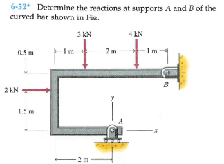
6-52 Determine the reactions at supports A and B of the curved bar shown in Fie. 3 kN 4 kN 0.5 m Im -2 m 1m B 2 kN 1.5 m 2 m


Q: 10. Determine the total support reactions at A and B for the truss loaded below. -5 at 3 m 15 m 12…
A: The free-body diagram of the structure is given as,
Q: 4 @ 4m=16m- A B C D G 60 kips L. -5@ 3m=15 m-
A:
Q: The total load W is to be lifted using the mast hinged at B. The mast is of uniform section and…
A: A tensile force is always going outward from its point of application. The mast is used for the…
Q: 6-91* A bar is supported by a ball-and-socket joint and two cables as shown in Fig. at support A…
A: Let point where downward force is acting be o Co-ordinates of points in question are A (0,0,0) B…
Q: 6-23. The Fink truss supports the loads shown. Determine the force in each member and state if the…
A:
Q: 6-6. Determine the force in each member of the truss, and state if the members are in tension or…
A:
Q: BONUS FOR QUIZ NO. 1 AND NO. 2 Given the Truss as shown below with load P and dimension L. Using…
A:
Q: 6-54.) Determine the force in members J/ and DE of the K truss. Indicate if the members are in…
A:
Q: 6-5. Determine the force in each member of the truss, and state if the members are in tension or…
A:
Q: 5-39. Determine the reactions at the supports A, C, and E of the compound beam. 12 kN 3 kN/m -3m- 6m
A:
Q: Solve for the reactions and the internal forces of all the members. SPACE TRUSS B D F-(100SN) |b E 4…
A:
Q: 40 kN -2 m- -2 m D 30° А, C В The truss above is supported by a roller at point A and a pin at point…
A:
Q: P5-2. Identify the zero-force members in each truss 800 N F3m 3 m 3 m-
A: Consider the free body diagram of the given truss as shown below. From the moment equilibrium about…
Q: Calculate the horizontal reaction at the hinge support A of the equilibrium rigid body shown in the…
A: The free body diagram of the beam is a follows:
Q: 6-13. Determine the force in each member of the truss in terms of the load P and state if the…
A:
Q: Member AB is supported by a roller at A and a pin at B. Draw the FBD and determine the reaction…
A: Let's mark the angle θ as shown in above figure, such that, sin θ= 1213 and cos θ= 513.
Q: 6-40 An angle bracket is loaded and supported as shown in Fig. Determine the reactions at supports A…
A: at Pt. A angle bracket has a pin joint and at Pt. B it has roller support. The free body diagram of…
Q: A drawbridge is being raised by a cable EI. The four joint loadings shown result from the weight of…
A:
Q: 6-47 A beam is loaded and supported as shown in Fig. The beam has a uniform cross section and weighs…
A: Given data: The weight of the beam is; w = 975 lb. The concentrated force acting at the right end of…
Q: 150 kN 3 m 60 200 kN B -2 panels at 4 m = 8 m EA = constant
A: given; →load at D ,(P1)=150KN→load at B (P2)=200KN with angle θ=600→BD=3m→AB=BC=4m→lets take…
Q: 6-43 Determine the reactions at supports A and B of the curved bar shown in Fig 30 50 Ib 6 in. 8…
A: Free-body diagram of the beam is given as, On taking equilibrium of forces in a horizontal…
Q: 6-34 A beam is loaded and supported as shown in Fig. The beam has a uniform cross section and a mass…
A: Given mass of beam (m) = 180 kg To determine Reactions at support A
Q: 6-95 A curved slender bar is loaded and supported as shown in Fig and B and the tension T in the…
A: Consider the free body diagram of the given figure as shown below.
Q: *5-28. Determine the force in members EF, BE, BC, and BF of the truss and state if these members are…
A: Given Applied load P1 = 9 kN P2 = 12 kN P3 = 6 kN To find Forces FEF FBE FBC FBF
Q: 6-37 A structural member is loaded and supported as shown in Fig. tion and weighs 208 lb. Determine…
A: Given Data: The weight of the member is W = 208 lb. The free-body diagram of the member can be…
Q: 6-48* A beam is loaded and supported as shown in Fig. The beam has a uniform cross section and a…
A: Given Data: The mass of the beam is M = 275 kg. The triangular load varies from w1 =0 to w2 = 4200…
Q: 6-30. Determine the force in members CD,HI,and CH of the truss, and state if the members are in…
A: Truss constitutes of various rods or bars in a specific pattern such that it can bear various forces…
Q: 6-51 A lever is loaded and supported as shown in Fig. Determine the force exerted on the lever by…
A: Given: The length of AB is AB =12 in. The length of AC is AC= 6 in. Calculate the length of CD by…
Q: The total load W is to be lifted using the mast hinged at B. The mast is of uniform section and…
A: GIVEN: Weight: W=36KN Length of rope AC : L=92+122=15m FREE BODY DIAGRAM: CALCULATING ANGLES:-…
Q: 6-33 A beam is loaded and supported as shown in Fig. The beam has a uniform cross section and weighs…
A: Given Data: Force applied on beam is F = 2500 lb. Length of beam is L = 12 ft. The weight of beam…
Q: *6-16. Determine the force in each member of the truss. State whether the members are in tension or…
A: GIVEN DATA A TRUSS IS GIVEN WE HAVE TO FIND FORCES IN ALL MEMBER
Q: 250 Ib סרן 3.18. The beam A is supported by a roller at B and is pin con- nected at C. tions at the…
A:
Q: *5-8. Determine the force in each member of the truss and state if the members are in tension or…
A: Given: P1=45 kNP1=30 kN At joint C Ballance the forces in x and y direction,…
Q: *5-24. Determine the force in members ED, EH, and GH of the truss and state if the members are in…
A: Given data To determine the forces in the members ED EH and GH
Q: 30 kip 5 kip/ft
A: To determine the support reaction at B we will first draw the free body diagram.
Q: 5-15. Determine the force in each member of the truss and state if the members are in tension or…
A:
Q: 6-96 Determine the reactions at supports A and B of the truss shown in Fig. 2 KN 3 kN 5 kN 2 m 2 m 2…
A: Calculate the angle formed by the forces with the horizontal as follows: tanθ=52θ=tan-152=68.20°…
Q: 7-18 Determine the forces in members BC, BE, and CE of the truss shown in Fig. The length of all…
A: Taking the forces at point D. The free body diagram is given below, The expression that can be…
Q: *5-56. Two smooth tubes A and B, each having the same wright, W, are anepended from a eommon point O…
A: The free-body diagram of the system is: In triangle ACO, the angle OAC is: In triangle ACD, the…
Q: 7-22 Determine the forces in members CD, DI, and HI of the truss shown in Fig. 18 kN 10 kN 14 kN E 3…
A: we have given truss in which three load acting on it. first we will find reacting force and then we…
Q: 6-11. Determine the force in each member of the Pratt truss, and state if the members are in tension…
A: A
Q: Determine the reaction at the support A of the frame. Supply the answer in kips (1000 Ibs).
A:
Q: 6-30. Determine the force in members CD, HI, and CH of the truss, and state if the members are in…
A: Solution: Cut a section X-X as shown below which passes through members CD, HI and CH:
Q: 6-47* A beam is loaded and supported as shown in Fig. The beam has a uniform cross section and…
A: Resolving the uniformly distributed load of magnitude 400 ×10= 4000 lb , which acts at the mid…
Q: 5-9 4) USE THE METHOD OF SECTIONS TO FIND THE MAGNITUDE AND DIRECTION OF THE FORCE IN MEMBER CD OF…
A:
Q: *6-44. Determine the force in members JI. EF. EI, and JE of the truss, and state if the members are…
A: GIVEN DATA A PLANE TRUSS GIVEN WE HAVE TO FIND FORCE IN GIVEN MEMBER OF TRUSSES
Q: *6-36. Determine the force in members BC, CG, and GF 3 m 3 m of the Warren truss. Indicate if the…
A:
Q: -24 in. +6 in.- 2. Determine the horizontal and vertical components of reaction of the pin B. (Ib) 4…
A: Consider vertically upward & horizontally forward force as (+)ve and vertically downward &…
Q: 6-78* The bent bar shown in Fig. two brackets that exert only force reactions on the bar. End C of…
A:
Q: 4/30 Determine the force in member CM of the loaded truss. 4m+4m+4m+4m4m+4m- E Fl K B N L L. L. A L…
A:

Step by step
Solved in 2 steps with 3 images

- The 20 mm diameter steel shaft AB is attached into the rigid wall at B and supported by a smooth bearing at A. The lever AC is welded to the end of the shaft. If the downward force P will produce a 50 mm vertical displacement at the free end of lever AC, determine the force P if G = 83 GPa.Can you Please Solve for Reaction @ Support A & B. Where EI constant.The assembly consists of two rigid bars that are originally horizontal. They are supported by pins and 0.25-in.-diameter A-36 steel rods. If the vertical load of 5 kip is applied to the bottom bar AB, determine the displacement at C, B, and E.
- For the bar shown below, determine the reaction at the support using (a) for stiffness method and (b) flexibility method.The pin at O can support a maximum force of 3.5 kN. What is the corresponding maximum load L which can be applied to the angled bracket AOB? A. 0.541 kN C. 2.632 kN B. 1.676 kN D. 3.091 kNUsing the method of sections, determine the forces inmembers BG, CI, and CD. Express your answers in terms of P (e.g.FA= 0.5P)3.1 Use the concepts of moment and force equilibrium, find the reactions atpoint A (FAx and FAy) and point E (FEy).3.2 Find FBG first. Cut through BC, BG, and GF, consider the Left-Hand Side(LHS) section as a whole, find FBG by considering the Free-Body Diagram(FBD), and equilibrium of forces in the y-direction.3.3 Now find FCI and FCD. Cut through CD, CI, and HI, consider the RHSsection as a whole, find FCI by considering the FBD, and equilibrium offorces in the y-direction. Then, find FCD by taking moment at point I, andconsider the concept of moment equilibrium.
- Determine the size of square bearing plates A′ and B′ required to support the loading. Take P = 1.5 kip. Dimension the plates to the nearest 1 2 in. The reactions at the supports are vertical and the allowable bearing stress for theplates is (sb)allow = 400 psi.Determine Reaction and Internal Member ForcesDetermine the load that can be applied at the end of the rigid bar if the stressin either spring shown in the figure shall not exceed 200MPa. Present detailed drawings/FBD’s illustrating your solution.
- The 2014-T6 aluminum strut is fixed between the two walls at A and B. If it has a 2 in. by 2 in. square cross-section, and it is subjected to the torsional loading shown, determine the reactions at the fixed supports. Also, what is the angle of twist at C?The link AB of the pliers has the cross section dimensions 3mm x 20mm, and is made of steel with elastic modulus E= 190 GPa. Determine the value of the force F that would cause failure of the link by bucklingCalculate the vertical reaction at support D. Enter your answer in kN to two decimal places.