(6) For the composite beam shown in the figure, which is bended about a horizontal axis by a couple of moment M = 1000 N · m, determine the maximum stresses in Materials A and B. Material A, E = 210 GPa 20 mm M 40 mm Material B, E = 69 GPa 20 mm
(6) For the composite beam shown in the figure, which is bended about a horizontal axis by a couple of moment M = 1000 N · m, determine the maximum stresses in Materials A and B. Material A, E = 210 GPa 20 mm M 40 mm Material B, E = 69 GPa 20 mm

Mechanics of Materials (MindTap Course List)
9th Edition
ISBN:9781337093347
Author:Barry J. Goodno, James M. Gere
Publisher:Barry J. Goodno, James M. Gere
Chapter6: Stresses In Beams (advanced Topics)
Section: Chapter Questions
Problem 6.2.3P: A composite beam consisting of fiberglass faces and a core of particle board has the cross section...

Related questions
Question
100%
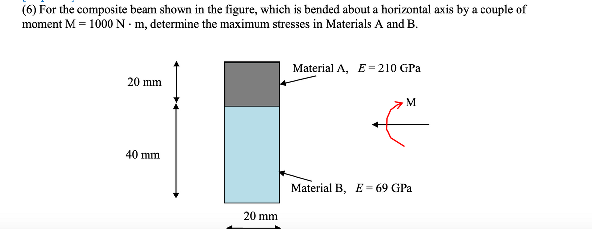
Transcribed Image Text:(6) For the composite beam shown in the figure, which is bended about a horizontal axis by a couple of
moment M = 1000 N · m, determine the maximum stresses in Materials A and B.
Material A, E=210 GPa
20 mm
M
40 mm
Material B, E= 69 GPa
20 mm
Expert Solution
This question has been solved!
Explore an expertly crafted, step-by-step solution for a thorough understanding of key concepts.

Step by step
Solved in 4 steps with 9 images

Knowledge Booster


Learn more about
Need a deep-dive on the concept behind this application? Look no further. Learn more about this topic, mechanical-engineering and related others by exploring similar questions and additional content below.Recommended textbooks for you
Mechanics of Materials (MindTap Course List)
Mechanical Engineering
ISBN:
9781337093347
Author:
Barry J. Goodno, James M. Gere
Publisher:
Cengage Learning
Mechanics of Materials (MindTap Course List)
Mechanical Engineering
ISBN:
9781337093347
Author:
Barry J. Goodno, James M. Gere
Publisher:
Cengage Learning