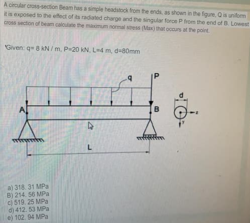
A circular cross-section Beam has a simple headstock from the ends, as shown in the figure, Q is uniform it is exposed to the effect of its radiated charge and the singular force P from the end of B. Lowest cross section of beam çalculate the maximum normal stress (Max) that occurs at the point.


Q: A column with a wide-flange section has a flange width b = 250 mm , height h = 250 m m, web…
A: Given dataWIdth of the flange w = 250mmHeight of the flange h = 250mmThinkness of the web tw=…
Q: A cantilever beam of length L= 1 m supports a load P = 8 kN, shown in figure. The beam is made of…
A:
Q: In the figure, find the length c of the overhangs so that the beam made of U profile can carry the…
A:
Q: A beam ABCD with a vertical arm CE is supported as simple beam at A and D as shown in the figure. A…
A: dear student please rate me positive Stay safe stay happy!
Q: A bending moment of M=150 kips-in is applied at the cross section of beam shown in Figure Question…
A:
Q: The constructed shear force diagram (SFD) for the simply supported beam with a Triangle distributed…
A:
Q: The figure shows a reinforced wooden beam with an aluminum channel section as seen in the figure.…
A: Given: The dimension of cross section is 6 in. by 10 in. Thickness is 0.25 in. Allowable stress in…
Q: 4.44 For the 8-in. I-beam shown in figure below, compute the maximum transverse shear stress (use…
A: First let us determine the moment of inertia of the section Moment of inertia about neutral axis =…
Q: maximum shear stress and normal stress in the beams.
A:
Q: (6) For the composite beam shown in the figure, which is bended about a horizontal axis by a couple…
A:
Q: A prismatic bar AB with a solid circular cross section (diameter d) is loaded by a distributed…
A: (a) To find: The maximum shear stress in the bar. Formula used: The maximum shear stress in the bar…
Q: 0.4 m y 0.2 m 0.3 m 0.6 m 5 m EFG kirişinin enine kesiti В 0.25 m 1200 N Q2) As shown in the figure,…
A: Given: The width of the cross-section, b = 25 mm The height of the cross-section, h = 50 mm The…
Q: Determine the maximum bending moment acting on the beam (ii) Develop for the beam, the expressions…
A: maxium bending moment will be at the bast of the cantilever its magnitude will be given by…
Q: situation; a) Maximum normal stress
A:
Q: Q2\ For the composite section beam shown in figure below. Determine the maximum bending stresses.…
A: ratio of elastic modulii = 200/25 = 8 we have to develop the equivalent section for solving the sum…
Q: For the box beam shown in Fig. if the modulus of elasticity E = 200 GPa, the %3D flexural stresses…
A:
Q: A simply supported beam -b<y<b, 0 <x<L, as shown below, is subjected to a compressive load of half…
A: σy= -3 4bx δ2Mδx2[y33b2-y] +c3f(x)+c4σy=0 at uy=-bc3f(x)+c4=34 δ2Mσx2 x 23= σy=-3…
Q: The figure below shows a simply supported beam with an overbang. The beam is made of two types of…
A: σpi=11 mPa Epi=8 GPaσpl=14 mPa Epl=12 GPaFind allowable magnitude w=?
Q: A cantilever beam with length, L = 5 m, is supporting a downward concentrated load, P = 88 kN, at…
A:
Q: Abeam with a rectangular cross section is simply supported and loaded at its center with a force P.…
A:
Q: The figure shows a cantilever consisting of steel angles size 100 x 100 x 12 mm mounted back to…
A: given data; ⇒w=1KN/mF=2.5KN⇒OA=2m⇒OB=3m⇒AB=1m
Q: A simply supported composite beam 3 m long carries a uniformly distributed load of intensity q = 3.0…
A:
Q: A beam ABC with an overhang from B to C supports a uniform load of200 lb/ft throughout its length…
A: (a) The reaction at the supports is calculated as : taking the moment about A as zero.…
Q: Example Fig. 4.19. If permissible stress is 150N/mm2, find its moment of resistance. Compare it with…
A: Area of I section = 7040 mm2 moment of inertia of I section; I = (bd3/12) - (b1d13/12)…
Q: A beam has a cross-sectional area as shown in the first figure. The lõàdš on the Bea moment diagram…
A:
Q: Consider a wood beam (see figure) carrying a uniform load of 13.5 kN/m (which includes the weight of…
A: In this part, each part is having 2 unknowns so we will solve first part for you. Please resubmit…
Q: The cross-section of beam shown in Figure Q2 (centroid in red) is subjected to pure bending. Taking…
A:
Q: A curved frame ABC is fixed at one end and subjected to a concentrated load P, as shown in Figure.…
A: →For section AB(0≤x≤L):-Mx=PxMx=0=MA=0Mx=L=MB=PL →For section BC:- Equation of moment at an angle…
Q: EIn the Figure below, a cantilever beam is subjected to an inclined force (P); calculate the: 1-…
A: (a) The normal stress: 144.3375 kPa. (b) The shear stress: 83.3333 kPa.
Q: A railroad tie (or sleeper) is subjected to two rail loads, each of magnitude P = 165 kN, acting as…
A:
Q: Ex: For a simple beam of length (L) subject to a concentrated load (P), shown in figure, Find : 1.…
A: Since, all the three parts are different question. And, as per the guidelines, I can solve only one…
Q: Consider the beam shown in sketch below, hinge supported at point A and roller supported at point D.…
A: Considering the cross-section of the beam The web is denoted as 1 and flange is denoted as 2
Q: A simply supported composite beam 2 m long carries a uniformly distributed load of intensity q = 2.3…
A: (a) To Find : The maximum bending σw and σs. Given : The uniformly distributed load intensity is :…
Q: For the beam shown in the figure, find the shear stress at a point 25 mm above the bottom of the…
A: Given, A simply supported beam with point load , P =14 KN Moment of inertia of the cross section ,…
Q: Box-section cantilever beam in the figure bears. Safety stresses in pressure and tension…
A: “Since you have posted a question with multiple sub-parts, we will solve first two subparts for you.…
Q: Figure Q2 shows the cross section of a beam. The beam is simply supported over a span of 6 m and…
A:
Q: In the beam loading system given below, A is a simple and C is a sliding support. The outer diameter…
A:
Q: Analyze the given beam that is subjected to a bending moment of 20 kg-m. Find the maximum stress…
A: An I section with unequal top and bottom width is given. And the bending moment acting on the beam…
Q: HOMEWORK: Q1/ A beam carries the loads shown in figure, if the tensile stress must not exceed 20 MPa…
A: Find load P
Q: Q2, For the composite section beam shown in figure below. Determine the maximum bending stresses.…
A: N = ratio of Elastic modulii= Esteel /Ewood = 10 we will now develop the equivalent beam
Q: The hollow circle cross section of the simply supported beam shown in the figure. Find the maximum…
A: For solution refer below images.
Q: Two tubular sections shown in Figure-2, have the same wall thickness and same circumference.…
A: Objective - To find the ratio of shear stresses for equal twisting moments for two cases.
Q: A bimetallic beam used in a temperature-control switch consists of strips of aluminum and coppe…
A:
Q: Q.2. A rectangular section 300 mm wide and 500 mm deep is used on a span of 6 m for the loading…
A:
Q: A composite beam consisting of fiberglass faces and a core of particle board has the cross section…
A:
Q: * The hollow circle cross section of the simply supported beam shown in the figure. Find the maximum…
A: For solution refer below images.
Q: Calculate the vertical shear stress (N / cm2) at point A in the critical section of the beam below…
A: Please refer to the detailed attached solution:

Step by step
Solved in 3 steps with 4 images


- A beam made up all woun equal leg angles is subjected to a bending moment M having its vector .u an angle (i) lo lire axis (see figure paria). (a) For the position shown in lire figure, determine lire orienlalion of lire neulral axis and calculate lire maximum tensile s'av-s ir, and maximum compressive stress (b) The two angles are now inverted and attached back-lo-back lo lorn, a lintel beam that supports two courses of brick facade i see figure part b). Find the new orientation of the neutral axis and calculate the maximum tensile slress r. a::d maximum compressive s'avsrr . in I he beam using 6 = 30° and M = 30 kip-in.A reinforced concrete beam (see figure) is acted on by a positive bending moment of M = 160 kN · m. Steel reinforcement consists of 4 bars of 28 mm diameter. The modulus of elasticity for the concrete is Ec= 25 GPa while that of the steel is Es= 200 GPa. Find the maximum stresses in steel and concrete. If allowable stresses for concrete and steel are T2= 9.2 MPa and t1= 135 MPa, respectively, what is the maximum permissible positive bending moment? What is the required area of steel reinforcement, A$ if a balanced condition must be achieved? What is the allowable positive bending moment? (Recall that in a balanced design, both steel and concrete reach allowable stress values simultaneously under the design moment.)A bimetallic beam used in a temperature-control switch consists of strips of aluminum and copper bonded together as shown in the figure, which is a cross-sectional view. The width of the beam is LO in,, and each strip has a thickness of 1/16 in. Under the action of a bending moment M = 12 lb-in, acting about the z axis, what are the maximum stresses aaand ecin the aluminum and copper, respectively? (Assume fA, = 10,5 x l0 psi and ecu= 16,8 × 10⁶ psi,)
- A reinforced concrete T-beam (see figure) is acted on by a positive bending moment of M = 175 kip-ft. Steel reinforcement consists of four bars of 1.41-inch diameter. The modulus of elasticity for the concrete is Ec= 3000 ksi while that of the steel is £s = 29,000 ksi. Let b = 48 im, rf = 4 in., bw=15 in,, and d = 24 in, Find the maximum stresses in steel and concrete, If allowable stresses for concrete and steel are o"ac = 1400 psi and tr^ =18 ksi, respectively, what is the maximum permissible positive bending moment?A beam is constructed of two angle sections, each L5 x 3 x 1/2, that reinforce a 2 x g (actual dimensions) wood plank (see the cross section shown in the figure). The modulus of elasticity for the wood is £w = L2 X 106 psi and for the steel is Es= 30 x 106 psi. Find the allowable bending moment M3][cmfor the beam if the allowable stress in the wood is trv= 1100 psi and in the steel is 3 = 12,000 psi. Note: Disregard the weight of the beam, and see Table F-5(a) of Appendix F for the dimensions and properties of the angles.A reinforced concrete slab (see figure) is reinforced with 13-mm bars spaced 160 mm apart at d = 105 mm from the top of the slab. The modulus of elasticity for the concrete is Ec= 25 GPa, while that of the steel is £s = 200 G Pa. Assume that allowable stresses for concrete and steel arecrac = 9.2 MPa and us = 135 MPa. l()5 mm Find the maximum permissible positive bending moment for a l-m wide strip of the slab. What is the required area of steel reinforcement, A^ if a balanced condition must be achieved? What is the allowable positive bending moment? (Recall that in a balanced design, both steel and concrete reach allowable stress values simultaneously under the design moment.)
- A r o lukI f/frm f «m t ub e of ou t sid e d ia met er ^ and a copper core of diameter dxare bonded to form a composite beam, as shown in the figure, (a) Derive formulas for the allowable bending moment M that can be carried by the beam based upon an allowable stress <7Ti in the titanium and an allowable stress (u in the copper (Assume that the moduli of elasticity for the titanium and copper are Er- and £Cu, respectively.) (b) If d1= 40 mm, d{= 36 mm, ETl= 120 GPa, ECu= 110 GPa, o-Ti = 840 MPa, and ctqj = 700 MPa, what is the maximum bending moment Ml (c) What new value of copper diameter dtwill result in a balanced design? (i.e., a balanced design is that in which titanium and copper reach allow- able stress values at the same time).A composite beam consisting of fiberglass faces and a core of particle board has the cross section shown in the figure. The width of the beam is 2,0 in., the thickness of the faces is 0,10 in., and the thickness of the core is 0.50 in. The beam is subjected to a bending moment of 250 lb-in, acting about the - axis. Find the maximum bending stresses tr(and ctc in the faces and the core, respectively, if their respective moduli of elasticity are 4 x 10⁶ psi and 1.5 x 10⁶ psi.Two flat beams AB and CD, lying in horizontal planes, cross at right angles and jointly support a vertical load P at their midpoints (see figure). Before the load P is applied, the beams just touch each other. Both beams are made of the same material and have the same widths. Also, the ends of both beams are simply supported. The lengths of beams AB and CD are LABand LCD, respectively. What should be the ratio tABltCDof the thicknesses of the beams if all four reactions arc to be the same?
- A C 200 x 17.1 channel section has an angle with equal legs attached as shown; the angle serves as a lintel beam. The combined steel section is subjected to a bending moment M having its vector directed along the z axis, as shown in the figure. The cent roi d C of the combined section is located at distances xtand ycfrom the centroid (C1) of the channel alone. Principal axes yl and yvare also shown in the figure and properties Ix1,Iy1and 0pare given. Find the orientation of the neutral axis and calculate the maximum tensile stress exand maximum compressive stress if the angle is an L 76 x 76 x 6.4 section and M = 3.5 kN - m. Use the following properties for principal axes for the combined section:/^, = 18.49 X 10⁶ nrai4,/;| = 1.602 X 106 mm4, ep= 7.448*(CW),_r£ = 10.70 mm,andvf= 24.07 mm.Two pipe columns (AB, FC) are pin-connected to a rigid beam (BCD), as shown in the figure. Each pipe column has a modulus of E, but heights (L1or L2) and outer diameters (d1or different for each column. Assume the inner diameter of each column is 3/4 of outer diameter. Uniformly distributed downward load q = 2PIL is applied over a distance of 3L/4 along BC, and concentrated load PIA is applied downward at D. (a) Derive a formula for the displacementThe cross section of a composite beam made of aluminum and steel is shown in the figure. The moduli of elasticity are TA= 75 GPa and Es= 200 GPa. Under the action of a bending moment that produces a maximum stress of 50 M Pa in the aluminum, what is the maximum stress xs in the steel? If the height of the beam remains at 120 mm and allowable stresses in steel and aluminum are defined as 94 M Pa and 40 M Pa, respectively, what heights h and h. arc required for aluminum and steel, respectively, so that both steel and aluminum reach their allowable stress values under the maximum moment?