
Database System Concepts
7th Edition
ISBN: 9780078022159
Author: Abraham Silberschatz Professor, Henry F. Korth, S. Sudarshan
Publisher: McGraw-Hill Education
expand_more
expand_more
format_list_bulleted
Related questions
Concept explainers
Question
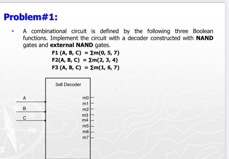

Transcribed Image Text:Problem#1:
A combinational circuit is defined by the following three Boolean
functions. Implement the circuit with a decoder constructed with NAND
gates and external NAND gates.
F1 (A, B, C) = Em(0, 5, 7)
F2(A, В, C) %3D 2m(2, 3, 4)
F3 (A, В, С) %3DZM(1, 6, 7)
Зx8 Decoder
mo
m1
B
m2
m3
m4
m5
m6
m7
Expert Solution
This question has been solved!
Explore an expertly crafted, step-by-step solution for a thorough understanding of key concepts.

This is a popular solution

Trending nowThis is a popular solution!

Step by stepSolved in 4 steps with 4 images

Knowledge Booster


Learn more about
Need a deep-dive on the concept behind this application? Look no further. Learn more about this topic, computer-science and related others by exploring similar questions and additional content below.Similar questions
- CREATING A CIRCUIT DIAGRAM Questions 4 and 5 refer to the function defined by the following truth table: w result 00001 00010 00110 00101 01101 01111 01010 0100 0 1 1000 1 1 0 1 0 1 111 0 11101 1 010 1 0 1 1 0 1 - 1 0010 1 000 1 Question 4 Fill in the values and draw the groupings of the Karnaugh Map. ५३ Wx 00 01. 11 10 00 01 11 10arrow_forwardConsider the following truth table. A 0 B001 В C Output 0 1 1 1 0 1 0 0 0 1 1 1 1 0 0 1 0 1 1 1 0 1 1 1 1 1a) 1b) Write the Boolean expression for the output using the sum-of-products (SOP) form. 1c) Draw the logic circuit using the expression derived in part (a). Use two-input gates (OR, AND) and single-input inverters. Write the Boolean expression for the output using product-of-sums (POS) form.arrow_forwardthis is from my digital system classarrow_forward
- The truth table for a Boolean expression is shown on figure1. A, B, C, D are inputs and Y is the output Write the Boolean expression on SOP form Y = f (A, B, C, D) Minimize the function using Karnaugh Map (K Map) Draw the minimized function using logic gatesarrow_forward1. A. Convert A5Q(27)→ X(9) 2. Simplify the Karnaugh maps and draw the logic circuit. AB 00 01 11 10 CD 00 1 1 1 1 01 1 1 11 1 1 10 1 1 11 1 AB 00 01 11 10 CD 00 1 1 01 11 1 1 10 11 11 1 1arrow_forwardA combinational circuit is described by this Boolean Expression: F(A,B,C,D) = 2m(0,2,4,8,9) i) Minimise the Boolean Expression given above using a Karnaugh map. ii) Given Don't Care conditions d = Em (10,11,12), use a separate Karnaugh map to demonstrate how you would further simplify the expression in part i). iii) Use Switching Algebra to show how you would implement the function obtained in part ii) by using NAND gates only. Provide a circuit diagram in your answer. Show all your working.arrow_forward
- The output of a combinational circuit which implements a majority function F(x,y,z) is equal to 1 if more input variables are equal to 1 rather than 0. The output is O otherwise, e.g. F(1,1,0)=1, F(0,0,1)=0. Which of the following expressions represent the simplified expression for function F? F = xy + xz + yz OF= xz + xy F = x + zy + z OF = x e y e zarrow_forwardImplement the diagram in part b and verify its function experimentally by constructing a truth table from the test data.arrow_forwardDraw the truth tables for the following Boolean expressions. xy+yz+xz x¯y+yz¯+x¯z (x⊕y)+(y⊕z)+(x⊕z) (xy)¯⊕ z 2.Draw circuit diagrams implementing each of the above expressions. You may simplify the expressions or not, as you choose. You may use any of the six fundamental logic gates (AND, OR, NOT, NAND, NOR and XOR). I need help on question 2 containing the circuit diagramsarrow_forward
- Given the following functions, F(A, B, C) = Em(0, 4, 6, 7) G(A, B, C) = [IM(1, 2, 3,4, 7) a. Implement both functions using a PROM chip (draw full grid) b. Implement both functions using as many 2:4 decoders chips (with a single active low enable) and any other logic gates needed in one circuit.arrow_forward1- In the following sequential circuit. There are 2 D FF (A and B), 2 inputs (x and y), and 1 output z The output and next-states equations are given A(t+1) = x'y + xA B(t+1) = x'B + xA z=B b- List the state table for the sequential circuit.arrow_forward
arrow_back_ios
arrow_forward_ios
Recommended textbooks for you
- Database System ConceptsComputer ScienceISBN:9780078022159Author:Abraham Silberschatz Professor, Henry F. Korth, S. SudarshanPublisher:McGraw-Hill Education
 Starting Out with Python (4th Edition)Computer ScienceISBN:9780134444321Author:Tony GaddisPublisher:PEARSON
 Digital Fundamentals (11th Edition)Computer ScienceISBN:9780132737968Author:Thomas L. FloydPublisher:PEARSON
  C How to Program (8th Edition)Computer ScienceISBN:9780133976892Author:Paul J. Deitel, Harvey DeitelPublisher:PEARSON
 Database Systems: Design, Implementation, & Manag...Computer ScienceISBN:9781337627900Author:Carlos Coronel, Steven MorrisPublisher:Cengage Learning
 Programmable Logic ControllersComputer ScienceISBN:9780073373843Author:Frank D. PetruzellaPublisher:McGraw-Hill Education
Database System Concepts
Computer Science
ISBN:9780078022159
Author:Abraham Silberschatz Professor, Henry F. Korth, S. Sudarshan
Publisher:McGraw-Hill Education
Starting Out with Python (4th Edition)
Computer Science
ISBN:9780134444321
Author:Tony Gaddis
Publisher:PEARSON
Digital Fundamentals (11th Edition)
Computer Science
ISBN:9780132737968
Author:Thomas L. Floyd
Publisher:PEARSON
C How to Program (8th Edition)
Computer Science
ISBN:9780133976892
Author:Paul J. Deitel, Harvey Deitel
Publisher:PEARSON
Database Systems: Design, Implementation, & Manag...
Computer Science
ISBN:9781337627900
Author:Carlos Coronel, Steven Morris
Publisher:Cengage Learning
Programmable Logic Controllers
Computer Science
ISBN:9780073373843
Author:Frank D. Petruzella
Publisher:McGraw-Hill Education