
Structural Analysis
6th Edition
ISBN: 9781337630931
Author: KASSIMALI, Aslam.
Publisher: Cengage,
expand_more
expand_more
format_list_bulleted
Related questions
Concept explainers
Question
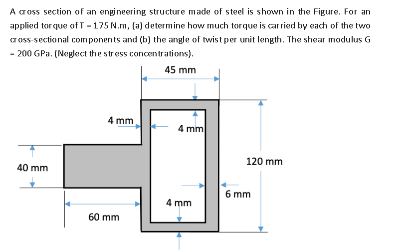

Transcribed Image Text:A cross section of an engineering structure made of steel is shown in the Figure. For an
applied torque of T = 175 N.m, (a) determine how much torque is carried by each of the two
cross-sectional components and (b) the angle of twist per unit length. The shear modulus G
= 200 GPa. (Neglect the stress concentrations).
45 mm
40 mm
4 mm
60 mm
4 mm
4 mm
120 mm
6 mm
Expert Solution
This question has been solved!
Explore an expertly crafted, step-by-step solution for a thorough understanding of key concepts.

Step by stepSolved in 2 steps with 1 images

Knowledge Booster


Learn more about
Need a deep-dive on the concept behind this application? Look no further. Learn more about this topic, civil-engineering and related others by exploring similar questions and additional content below.Similar questions
- The rectangular plate is subjected to force P that causes elongation in the horizontal direction and shrinking in the vertical direction as shown with the dashed line in the figure. Assume a = 550 mm, Δx = 2 mm, and Δy = 1.1 mm. Determine the shear strain γxy at point A? Determine the shear strain γnt at point A? In micro rad What is the normal strain in the x-direction? What is the normal strain in the y-direction? What is the normal strain in the n-direction? Answer in clear way pleasearrow_forwardAt a point on the surface of a generator shaft, the stresses are shown on the stress element in the figure. Using Mohr's circle, determine the following: • The stresses acting on an inclined at an angle 0= 45° CCW • The principal stresses • The maximum shear stresses. • Show all results on sketches of properly oriented elements. 0 10 MPa 50 MPa 40 MPaarrow_forwardMohr's circle is shown for a point in a physical object that is subjected to plane stress. Each grid square is 780 psi in size. (a) Determine the stresses O, Oy, and the magnitude of Tyand show them on a stress element. (b) Determine the principal stresses and the magnitude of the maximum in-plane shear stress acting at the point and show these stresses on an appropriate sketch (e.g., see Figure 12.15 or Figure 12.16). y Answer: (a) ox = i psi Oy = psi Txy = psi (b) Op1 = i psi Op2 = i psi Tmax in-plane " i psiarrow_forward
- Mohr's circle is shown for a point in a physical object that is subjected to plane stress. Each grid square is 280 psi in size. (a) Determine the stresses Ox, Oy, and the magnitude of Tyand show them on a stress element. (b) Determine the principal stresses and the magnitude of the maximum in-plane shear stress acting at the point and show these stresses on an appropriate sketch (e.g., see Figure 12.15 or Figure 12.16). y Answer: (a) Ox = i ! psi Oy= i ! psi %3D Txy = psi (b) Op1 = i psi Op2 = i psi Tmax in-plane psiarrow_forwardMohr's circle is shown for a point in a physical object that is subjected to plane stress. Each grid square is 540 psi in size. (a) Determine the stresses Ox, Oy, and the magnitude of Txy and show them on a stress element. (b) Determine the principal stresses and the magnitude of the maximum in-plane shear stress acting at the point and show these stresses on an appropriate sketch (e.g., see Figure 12.15 or Figure 12.16). Answer: (a) ox= i Oy= i Txy = (b) Op1 = Op2 i Tmax in-plane y C psi psi psi X psi psi psi σarrow_forwardA 52-kip force acts on a machine part at point A as shown below. The diagram shows the internal normal force, shear force and bending moment acting on a particular RECTANGULAR Cross section. -30in N 10in 26in F=52 kip The value of the bending moment M you would use to find the bending stress on a stress element located 2 inches up from the bottom of the rectangular cross section is closest to: 264 kip-in O a. 408 kip-in Ob. 1,464 kip-in O c. 1,608 kip-inarrow_forward
- Mohr's circle is shown for a point in a physical object that is subjected to plane stress. Each grid square is 220 psi in size. (a) Determine the stresses Ox, Oy, and the magnitude of Txy and show them on a stress element. (b) Determine the principal stresses and the magnitude of the maximum in-plane shear stress acting at the point and show these stresses on an appropriate sketch (e.g., see Figure 12.15 or Figure 12.16). Answer: (a) ox= i Oy = Txy = i i (b) Op1 = i op2 = i max in-plane y i C psi psi psi X psi psi psi σarrow_forwardThin square plate PQRS is symmetrically deformed into the shape shown by the dashed lines in the figure.[a = 200 mm, b = 202.1 mm, c = 198.9 mm] For the deformed plate, determine the normal strain of diagonal PR? In micro £ For the deformed plate, determine the shear strain xy at corner P?in micro radarrow_forwardA thin rectangular plate ABCD is deformed into a parallelogram as shown in the figure below. The width of the plate is w = 1300 mm, and the height of the plate is h = 1700 mm. The shear strain at A is known to be +4172 μrad. Assume a = 2.9 mm. Calculate the magnitude of dimension b in the figure.arrow_forward
- Nonearrow_forwardThe cross-sectional dimensions of a beam are shown in the figure. (a) If the bending stress at point K is 35 MPa (C), determine the internal bending moment Mz acting about the z centroidal axis of the beam. (b) Determine the bending stress at point H. The bending stress is positive if in tension and negative if in compression. 85 mm 4 mm TT K 55 mm H 4 mm 45 mm 4 mm Answers: (a) Mz = UN-m (b) OH = JMPAarrow_forwardThe tubular shaft shown in the figure has an external diameter of D = 5.5 in. and an internal diameter of d = 2.75 in. and is subjected to a torque of T= 6825 lb-in. [theta = 31 deg] What is the shear stress at A?in psi What is the shear stress at B?in psi What is the shear stress at C? What is the shear stress at D?in psi What is the shear stress at E?in psiarrow_forward
arrow_back_ios
arrow_forward_ios
Recommended textbooks for you
 Structural Analysis (10th Edition)Civil EngineeringISBN:9780134610672Author:Russell C. HibbelerPublisher:PEARSON
 Principles of Foundation Engineering (MindTap Cou...Civil EngineeringISBN:9781337705028Author:Braja M. Das, Nagaratnam SivakuganPublisher:Cengage Learning
 Fundamentals of Structural AnalysisCivil EngineeringISBN:9780073398006Author:Kenneth M. Leet Emeritus, Chia-Ming Uang, Joel LanningPublisher:McGraw-Hill Education
 Traffic and Highway EngineeringCivil EngineeringISBN:9781305156241Author:Garber, Nicholas J.Publisher:Cengage Learning
Structural Analysis (10th Edition)
Civil Engineering
ISBN:9780134610672
Author:Russell C. Hibbeler
Publisher:PEARSON
Principles of Foundation Engineering (MindTap Cou...
Civil Engineering
ISBN:9781337705028
Author:Braja M. Das, Nagaratnam Sivakugan
Publisher:Cengage Learning
Fundamentals of Structural Analysis
Civil Engineering
ISBN:9780073398006
Author:Kenneth M. Leet Emeritus, Chia-Ming Uang, Joel Lanning
Publisher:McGraw-Hill Education
Traffic and Highway Engineering
Civil Engineering
ISBN:9781305156241
Author:Garber, Nicholas J.
Publisher:Cengage Learning