(a) Three identical loads Zy, each of resistance 50 and inductance of 16 mH are connected to a three phase supply as shown in Figure Q4a. The supply has a line to line voltage of 415 V with 30° phase angle and operates at frequency of 50 Hz. Determine: (1) The total power dissipated in the loads. (ii) The total reactive power of the loads. Van Figure Q4a
(a) Three identical loads Zy, each of resistance 50 and inductance of 16 mH are connected to a three phase supply as shown in Figure Q4a. The supply has a line to line voltage of 415 V with 30° phase angle and operates at frequency of 50 Hz. Determine: (1) The total power dissipated in the loads. (ii) The total reactive power of the loads. Van Figure Q4a

Power System Analysis and Design (MindTap Course List)
6th Edition
ISBN:9781305632134
Author:J. Duncan Glover, Thomas Overbye, Mulukutla S. Sarma
Publisher:J. Duncan Glover, Thomas Overbye, Mulukutla S. Sarma
Chapter6: Power Flows
Section: Chapter Questions
Problem 6.61P

Related questions
Question
100%
Example 6:-
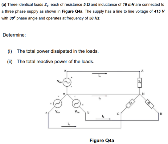
Transcribed Image Text:(a) Three identical loads Zy, each of resistance 50 and inductance of 16 mH are connected to
a three phase supply as shown in Figure Q4a. The supply has a line to line voltage of 415 V
with 30° phase angle and operates at frequency of 50 Hz.
Determine:
(i) The total power dissipated in the loads.
(ii) The total reactive power of the loads.
Van
Ven
b
Figure Q4a
Expert Solution
This question has been solved!
Explore an expertly crafted, step-by-step solution for a thorough understanding of key concepts.

Step by step
Solved in 3 steps with 3 images

Knowledge Booster


Learn more about
Need a deep-dive on the concept behind this application? Look no further. Learn more about this topic, electrical-engineering and related others by exploring similar questions and additional content below.Recommended textbooks for you
Power System Analysis and Design (MindTap Course …
Electrical Engineering
ISBN:
9781305632134
Author:
J. Duncan Glover, Thomas Overbye, Mulukutla S. Sarma
Publisher:
Cengage Learning
Power System Analysis and Design (MindTap Course …
Electrical Engineering
ISBN:
9781305632134
Author:
J. Duncan Glover, Thomas Overbye, Mulukutla S. Sarma
Publisher:
Cengage Learning