(b) A synchronous generator connected with an equivalent cireuit of Figure Q4 is shown as below. Here, the armature resistance is being ignored. The field current is adjusted so that the terminal voltage is 480 V at no load. Develop and sketch the output phase voltage vs. load current characteristics of the generator under these condition as below: - i) 0.8 p.f. lagging load for 10 A, 30 A and 60 A load current ii) 0.8 p.f. leading load for 10 A, 30 A and 60 A load current Based on the characteristics as above, explain the changes of output phase voltage from the generator. Suggest the method to overcome of the instability of output phase voltage as shown? RA IA 0.2 2 j1.0 2 RĘ VF LF Figure Q4: Synchronous generator equivalent circuit
(b) A synchronous generator connected with an equivalent cireuit of Figure Q4 is shown as below. Here, the armature resistance is being ignored. The field current is adjusted so that the terminal voltage is 480 V at no load. Develop and sketch the output phase voltage vs. load current characteristics of the generator under these condition as below: - i) 0.8 p.f. lagging load for 10 A, 30 A and 60 A load current ii) 0.8 p.f. leading load for 10 A, 30 A and 60 A load current Based on the characteristics as above, explain the changes of output phase voltage from the generator. Suggest the method to overcome of the instability of output phase voltage as shown? RA IA 0.2 2 j1.0 2 RĘ VF LF Figure Q4: Synchronous generator equivalent circuit

Power System Analysis and Design (MindTap Course List)
6th Edition
ISBN:9781305632134
Author:J. Duncan Glover, Thomas Overbye, Mulukutla S. Sarma
Publisher:J. Duncan Glover, Thomas Overbye, Mulukutla S. Sarma
Chapter11: Transient Stability
Section: Chapter Questions
Problem 11.3P

Related questions
Question
Transcribed Image Text:(b)
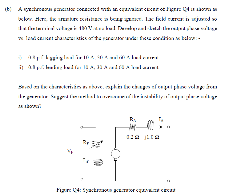
A synchronous generator connected with an equivalent circuit of Figure Q4 is shown as
below. Here, the armature resistance is being ignored. The field current is adjusted so
that the terminal voltage is 480 V at no load. Develop and sketch the output phase voltage
vs. load current characteristics of the generator under these condition as below: -
i) 0.8 p.f. lagging load for 10 A, 30 A and 60 A load current
ii) 0.8 p.f. leading load for 10 A, 30 A and 60 A load current
Based on the characteristies as above, explain the changes of output phase voltage from
the generator. Suggest the method to overcome of the instability of output phase voltage
as shown?
RA
IA
0.2 2 j1.0 2
RF
VF
LF
Figure Q4: Synchronous generator equivalent circuit
Expert Solution
This question has been solved!
Explore an expertly crafted, step-by-step solution for a thorough understanding of key concepts.

Step by step
Solved in 6 steps with 3 images

Knowledge Booster


Learn more about
Need a deep-dive on the concept behind this application? Look no further. Learn more about this topic, electrical-engineering and related others by exploring similar questions and additional content below.Recommended textbooks for you
Power System Analysis and Design (MindTap Course …
Electrical Engineering
ISBN:
9781305632134
Author:
J. Duncan Glover, Thomas Overbye, Mulukutla S. Sarma
Publisher:
Cengage Learning
Power System Analysis and Design (MindTap Course …
Electrical Engineering
ISBN:
9781305632134
Author:
J. Duncan Glover, Thomas Overbye, Mulukutla S. Sarma
Publisher:
Cengage Learning