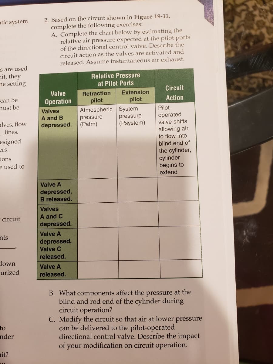
Based on the circuit shown in Figure 19-11, complete the following exercises: A. Complete the chart below by estimating the relative air pressure expected at the pilot ports of the directional control valve. Describe the circuit action as the valves are activated and released. Assume instantaneous air exhaust.
Based on the circuit shown in Figure 19-11, complete the following exercises: A. Complete the chart below by estimating the relative air pressure expected at the pilot ports of the directional control valve. Describe the circuit action as the valves are activated and released. Assume instantaneous air exhaust.

Elements Of Electromagnetics
7th Edition
ISBN:9780190698614
Author:Sadiku, Matthew N. O.
Publisher:Sadiku, Matthew N. O.
ChapterMA: Math Assessment
Section: Chapter Questions
Problem 1.1MA

Related questions

Question
Transcribed Image Text:atic system
2. Based on the circuit shown in Figure 19-11,
complete the following exercises:
A. Complete the chart below by estimating the
relative air pressure expected at the pilot ports
of the directional control valve. Describe the
circuit action as the valves are activated and
released. Assume instantaneous air exhaust.
s are used
hit, they
he setting
Relative Pressure
at Pilot Ports
Circuit
Valve
Retraction
Extension
can be
nust be
Operation
pilot
pilot
Action
Atmospheric System
pressure
(Psystem)
Valves
Pilot-
A and B
depressed.
pressure
(Patm)
operated
valve shifts
alves, flow
allowing air
to flow into
blind end of
lines.
esigned
ers.
ions
e used to
the cylinder,
cylinder
begins to
extend
Valve A
depressed,
B released.
Valves
A and C
depressed.
circuit
Valve A
nts
depressed,
Valve C
released.
down
-urized
Valve A
released.
B. What components affect the pressure at the
blind and rod end of the cylinder during
circuit operation?
C. Modify the circuit so that air at lower pressure
can be delivered to the pilot-operated
directional control valve. Describe the impact
of
to
nder
your modification on circuit operation.
ait?
Transcribed Image Text:NVIDIA
GEFORCE
GTX
(intel)
CORE I7
Bth Gen
Chapter 19 Applying Pneumatic Power
475
Valve B
Valve C
Extension pilot
Retraction pilot
Valve A
Goodheart-Willcox Publisher
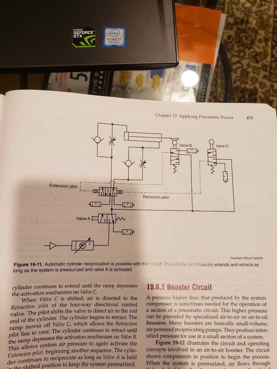
Figure 19-11. Automatic cylinder reciprocation is possible with this circult The cylinter continuously extends and retracts as
long as the system is pressurized and valve A is activated.
cylinder continues to extend until the ramp depresses
the activation mechanism on Valve C.
When Valve C is shifted, air is directed to the
Retraction pilot of the four-way directional control
valve. The pilot shifts the valve to direct air to the rod
end of the cylinder. The cylinder begins to retract. The
ramp moves off Valve C, which allows the Retraction
pilot line to vent. The cylinder continues to retract until
the ramp depresses the activation mechanism on Valve B
This allows system air pressure to again activate the
Extension pilot, beginning another sequence. The cylin-
der continues to reciprocate as long as Valve A is held
in the shifted position to keep the system pressurized.
19.6.1 Booster Circuit
A pressure higher than that produced by the system
compressor is sometimes needed for the operation of
a section of a pneumatic circuit. This higher pressure
can be provided by specialized air-to-air or air-to-oil
boosters. Many boosters are basically small-volume,
air-powered reciprocating pumps. They produce inten-
sified pressure for use in a small section of a system.
Figure 19-12 illustrates the circuit and operating
concepts involved in an air-to-air booster. The circuit
shows components in position to begin the process.
When the system is pressurized, air flows through
1 111
Expert Solution
This question has been solved!
Explore an expertly crafted, step-by-step solution for a thorough understanding of key concepts.

This is a popular solution!

Trending now
This is a popular solution!

Step by step
Solved in 2 steps with 1 images

Knowledge Booster


Learn more about
Need a deep-dive on the concept behind this application? Look no further. Learn more about this topic, mechanical-engineering and related others by exploring similar questions and additional content below.Recommended textbooks for you
Elements Of Electromagnetics
Mechanical Engineering
ISBN:
9780190698614
Author:
Sadiku, Matthew N. O.
Publisher:
Oxford University Press

Mechanics of Materials (10th Edition)
Mechanical Engineering
ISBN:
9780134319650
Author:
Russell C. Hibbeler
Publisher:
PEARSON

Thermodynamics: An Engineering Approach
Mechanical Engineering
ISBN:
9781259822674
Author:
Yunus A. Cengel Dr., Michael A. Boles
Publisher:
McGraw-Hill Education
Elements Of Electromagnetics
Mechanical Engineering
ISBN:
9780190698614
Author:
Sadiku, Matthew N. O.
Publisher:
Oxford University Press
Mechanics of Materials (10th Edition)
Mechanical Engineering
ISBN:
9780134319650
Author:
Russell C. Hibbeler
Publisher:
PEARSON
Thermodynamics: An Engineering Approach
Mechanical Engineering
ISBN:
9781259822674
Author:
Yunus A. Cengel Dr., Michael A. Boles
Publisher:
McGraw-Hill Education

Control Systems Engineering
Mechanical Engineering
ISBN:
9781118170519
Author:
Norman S. Nise
Publisher:
WILEY

Mechanics of Materials (MindTap Course List)
Mechanical Engineering
ISBN:
9781337093347
Author:
Barry J. Goodno, James M. Gere
Publisher:
Cengage Learning

Engineering Mechanics: Statics
Mechanical Engineering
ISBN:
9781118807330
Author:
James L. Meriam, L. G. Kraige, J. N. Bolton
Publisher:
WILEY