Consider the circuit depicted in the figure shown below. This circuit is designed using a silicon bipolar junction transistor (BJT) with a forwar gain BF = 100, and two resistances RB = 1kN and Rc = 1kN. The supply voltage is Vcc = 10 volts. The currents Ig and Ic designate the base and collector currents, respectively, whereas the voltage VCg denotes the voltage between colle emitter. Vcc = 10 volts Rc =1 kN RB = 1 kN Vce GND Throughout this question, you will use VBE,on = 0.7 volt and VCE,sat = 0.2 volt.
Consider the circuit depicted in the figure shown below. This circuit is designed using a silicon bipolar junction transistor (BJT) with a forwar gain BF = 100, and two resistances RB = 1kN and Rc = 1kN. The supply voltage is Vcc = 10 volts. The currents Ig and Ic designate the base and collector currents, respectively, whereas the voltage VCg denotes the voltage between colle emitter. Vcc = 10 volts Rc =1 kN RB = 1 kN Vce GND Throughout this question, you will use VBE,on = 0.7 volt and VCE,sat = 0.2 volt.

Introductory Circuit Analysis (13th Edition)
13th Edition
ISBN:9780133923605
Author:Robert L. Boylestad
Publisher:Robert L. Boylestad
Chapter1: Introduction
Section: Chapter Questions
Problem 1P: Visit your local library (at school or home) and describe the extent to which it provides literature...

Related questions
Question
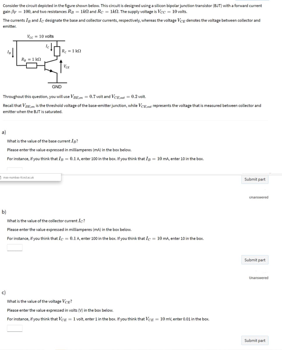
Transcribed Image Text:Consider the circuit depicted in the figure shown below. This circuit is designed using a silicon bipolar junction transistor (BJT) with a forward current
gain BF = 100, and two resistances RB = 1kN and Rc = 1kN. The supply voltage is Vcc = 10 volts.
The currents Ig and Ic designate the base and collector currents, respectively, whereas the voltage VCẸ denotes the voltage between collector and
emitter.
Vcc = 10 volts
Rc =1 k2
Rg = 1 k2
VCE
GND
Throughout this question, you will use VBE,on = 0.7 volt and VCE,sat = 0.2 volt.
Recall that VBE.on is the threshold voltage of the base-emitter junction, while VCE.sat represents the voltage that is measured between collector and
emitter when the BJT is saturated.
a)
What is the value of the base current In?
Please enter the value expressed in milliamperes (mA) in the box below.
For instance, if you think that IR = 0.1 A, enter 100 in the box. If you think that Ip = 10 mA, enter 10 in the box.
mas-numbas-Iti.ncl.ac.uk
Submit part
Unanswered
b)
What is the value of the collector current Ic?
Please enter the value expressed in milliamperes (mA) in the box below.
For instance, if you think that Ic = 0.1 A, enter 100 in the box. If you think that Ic = 10 mA, enter 10 in the box.
Submit part
Unanswered
c)
What is the value of the voltage VCE?
Please enter the value expressed in volts (V) in the box below.
For instance, if you think that VCE = 1 volt, enter 1 in the box. If you think that VCE = 10 mV, enter 0.01 in the box.
Submit part
Expert Solution
This question has been solved!
Explore an expertly crafted, step-by-step solution for a thorough understanding of key concepts.

Step by step
Solved in 3 steps

Knowledge Booster


Learn more about
Need a deep-dive on the concept behind this application? Look no further. Learn more about this topic, electrical-engineering and related others by exploring similar questions and additional content below.Recommended textbooks for you
Introductory Circuit Analysis (13th Edition)
Electrical Engineering
ISBN:
9780133923605
Author:
Robert L. Boylestad
Publisher:
PEARSON

Delmar's Standard Textbook Of Electricity
Electrical Engineering
ISBN:
9781337900348
Author:
Stephen L. Herman
Publisher:
Cengage Learning

Programmable Logic Controllers
Electrical Engineering
ISBN:
9780073373843
Author:
Frank D. Petruzella
Publisher:
McGraw-Hill Education
Introductory Circuit Analysis (13th Edition)
Electrical Engineering
ISBN:
9780133923605
Author:
Robert L. Boylestad
Publisher:
PEARSON
Delmar's Standard Textbook Of Electricity
Electrical Engineering
ISBN:
9781337900348
Author:
Stephen L. Herman
Publisher:
Cengage Learning
Programmable Logic Controllers
Electrical Engineering
ISBN:
9780073373843
Author:
Frank D. Petruzella
Publisher:
McGraw-Hill Education

Fundamentals of Electric Circuits
Electrical Engineering
ISBN:
9780078028229
Author:
Charles K Alexander, Matthew Sadiku
Publisher:
McGraw-Hill Education

Electric Circuits. (11th Edition)
Electrical Engineering
ISBN:
9780134746968
Author:
James W. Nilsson, Susan Riedel
Publisher:
PEARSON

Engineering Electromagnetics
Electrical Engineering
ISBN:
9780078028151
Author:
Hayt, William H. (william Hart), Jr, BUCK, John A.
Publisher:
Mcgraw-hill Education,