
Introductory Circuit Analysis (13th Edition)
13th Edition
ISBN: 9780133923605
Author: Robert L. Boylestad
Publisher: PEARSON
expand_more
expand_more
format_list_bulleted
Related questions
Question
Don't use ai to answer I will report you answer
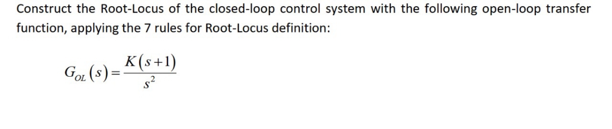

Transcribed Image Text:Construct the Root-Locus of the closed-loop control system with the following open-loop transfer
function, applying the 7 rules for Root-Locus definition:
GOL (s) = K(s+1)
2
Expert Solution
This question has been solved!
Explore an expertly crafted, step-by-step solution for a thorough understanding of key concepts.

Step by stepSolved in 2 steps with 13 images

Knowledge Booster

Similar questions
- d) Write the poles that will yield the required response (OS =10% and Ts=1.2 sec) for the closed loop system 1 (s+1) (s +2)(s+3)(s+5) Input Output ??? ??? State Feedback and at the same time will reduce the order of the final system to two. % determine the poles of the closed loop system % p2 =arrow_forwardDo b)arrow_forwardThe output response is as in figure-b, while applying the unitstep function to the system input given in the figure-family block diagram belowis happening. T and are the constant numbers seen in the open loop transfer function. Calculate the constant.arrow_forward
- Consider the control system shown in Figure 1. Copy it into your answer book, labelling the actual output, control signal, desired output, plant, proportional action and derivative action. Also write down the control algorithm. Q1 (a) + s+1 kas I+ s+ 5 kp Figure 1 Determine the open-loop transfer function for the system shown in Figure 1 and hence obtain an expression for the closed-loop transfer function. (b) Find the state-space representation in phase-variable form for the above closed- loop system. Assume kp = 2 and ka = 1. (c) (d) Draw a signal flow diagram for the above system, assuming phase-variable form.arrow_forward2 parts (A-B) SOLVE CAREFULLY!! Please Write Clearly and Box the final Answer(s) label themarrow_forwardQ2 Figure Q2a shows the block diagram of a control system. Using the block diagram reduction method, determine the closed loop transfer function of the system shown in Figure Q2a. Show all intermediate steps in the reduction process including block diagrams and working. (а) The transfer functions of the blocks in Q2a are as follows: G1(s) = ! G2(s) = s G3(s) = s² H1(s) = s H2(s) = 2s R(s), C(s) GI(s) G2(s) G3(s) H1(s) H2(s) Figure Q2a Continued overleaf Page 3 of 12 (b) Determine the range of K for which the system shown in figure Q2b is stable. R(s) E(s) C(s) 1 s2 + 10s + 10 Figure Q2barrow_forward
- 3. The block diagram given here shows a closed-loop control of a third order plant. Comment on the stability of (i) the open-loop transfer function and (ii) closed-loop transfer function using Routh-Hurwitz stability criterion. What should be the appropriate value(s) of K to have stability in closed-loop control? R(s) - K s+1 s3 + s² + 2s+8 C(s)arrow_forwardSimplify the block diagram shown in Figure 1 and obtain the closed-loop transfer function ?(?)/?(?).arrow_forward3. A robot force control system with unity feedback has a loop transfer function K(s +2.5) (s² +2s+2)(s² + 4s+4) KL(s) = KG(s) =- Find break-in and breakaway points (if any). b. Find the jw-axis crossing and the gain, K, at the crossing. c. Determine the range of K stability.arrow_forward
- Please explain each step clearly and include a proper image of what the block diagram and plot must look like. thank youarrow_forwardThe previous solutions are posted on screenshot. please refer to them for gain value. solve : An integrator is added to the PD controller, leading to a PID controller C(s) = kp +ki/s + kds. Keep the PD controllers gains kp and kd from above, and plot the closed-loop poles as the gain ki varies from 0 ! 1 (Hint: The closed-loop poles satisfy 1 + P (s)C(s) = 0, translate this to Evan’s form 1 + kiG(s) = 0). Determine gains such that a load disturbance is rejected in about 10 time units, while keeping the amount of overshoot (from r to y) under 20%. Why can ki not be too large?arrow_forwardQ2 A PID controller is designed to control the robot leg, and the control system is shown in Figure 2 where K is a positive gain. (a) (b) R(S) Find the closed-loop transfer function (s)/R (s). Use the Routh-Hurwitz stability criterion to determine the range of the parameter K such that the closed-loop system is stable. K 1+-+s S PID Controller 2 s² + 3s +2 Robot Leg dynamics Figure 2 e(s)arrow_forward
arrow_back_ios
SEE MORE QUESTIONS
arrow_forward_ios
Recommended textbooks for you
- Introductory Circuit Analysis (13th Edition)Electrical EngineeringISBN:9780133923605Author:Robert L. BoylestadPublisher:PEARSON
 Delmar's Standard Textbook Of ElectricityElectrical EngineeringISBN:9781337900348Author:Stephen L. HermanPublisher:Cengage Learning
 Programmable Logic ControllersElectrical EngineeringISBN:9780073373843Author:Frank D. PetruzellaPublisher:McGraw-Hill Education
  Fundamentals of Electric CircuitsElectrical EngineeringISBN:9780078028229Author:Charles K Alexander, Matthew SadikuPublisher:McGraw-Hill Education
 Electric Circuits. (11th Edition)Electrical EngineeringISBN:9780134746968Author:James W. Nilsson, Susan RiedelPublisher:PEARSON
 Engineering ElectromagneticsElectrical EngineeringISBN:9780078028151Author:Hayt, William H. (william Hart), Jr, BUCK, John A.Publisher:Mcgraw-hill Education,
Introductory Circuit Analysis (13th Edition)
Electrical Engineering
ISBN:9780133923605
Author:Robert L. Boylestad
Publisher:PEARSON
Delmar's Standard Textbook Of Electricity
Electrical Engineering
ISBN:9781337900348
Author:Stephen L. Herman
Publisher:Cengage Learning
Programmable Logic Controllers
Electrical Engineering
ISBN:9780073373843
Author:Frank D. Petruzella
Publisher:McGraw-Hill Education
Fundamentals of Electric Circuits
Electrical Engineering
ISBN:9780078028229
Author:Charles K Alexander, Matthew Sadiku
Publisher:McGraw-Hill Education
Electric Circuits. (11th Edition)
Electrical Engineering
ISBN:9780134746968
Author:James W. Nilsson, Susan Riedel
Publisher:PEARSON
Engineering Electromagnetics
Electrical Engineering
ISBN:9780078028151
Author:Hayt, William H. (william Hart), Jr, BUCK, John A.
Publisher:Mcgraw-hill Education,