Design a clocked synchronous state machine with the state/output table shown in the table below, using Rising Edge Triggered (RET) D flip-flops. Use two state variables, Q1, Qo, with state assignments (S=Q1Q0) of A=00, B=01, C=11 and D=10. XY State 00 01 11 10 Z (output) A В C D 1 B D A D C D B D 1 D C B B Next State Expectations for designing the circuit. Show all work. Use the state variable and state assignments given Develop and provide the transition/output table Develop excitation equations, these are expected to minimized sum of products forms Develop output equation(s), these are expected to minimized sum of products forms Draw the complete logic circuit UMAA
Design a clocked synchronous state machine with the state/output table shown in the table below, using Rising Edge Triggered (RET) D flip-flops. Use two state variables, Q1, Qo, with state assignments (S=Q1Q0) of A=00, B=01, C=11 and D=10. XY State 00 01 11 10 Z (output) A В C D 1 B D A D C D B D 1 D C B B Next State Expectations for designing the circuit. Show all work. Use the state variable and state assignments given Develop and provide the transition/output table Develop excitation equations, these are expected to minimized sum of products forms Develop output equation(s), these are expected to minimized sum of products forms Draw the complete logic circuit UMAA

Chapter22: Sequence Control
Section: Chapter Questions
Problem 6SQ: Draw a symbol for a solid-state logic element AND.

Related questions
Question
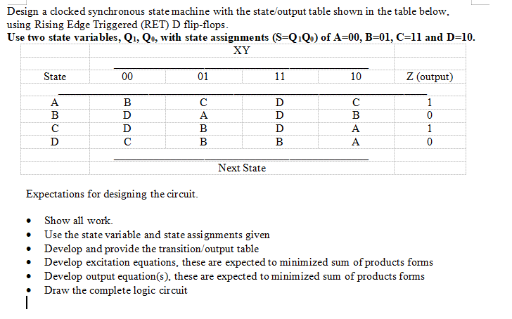
Transcribed Image Text:Design a clocked synchronous statemachine with the state/output table shown in the table below,
using Rising Edge Triggered (RET) D flip-flops.
Use two state variables, Q1, Qo, with state assignments (S=Q1Q0) of A=00, B=01, C=11 and D=10.
XY
State
00
01
11
10
Z (output)
A
B
C
D
1
B
D
A
D
C
D
B
D
1
D
C
B
B
Next State
Expectations for designing the circuit.
• Show all work.
• Use the state variable and state assignments given
Develop and provide the transition/output table
• Develop excitation equations, these are expected to minimized sum of products forms
• Develop output equation(s), these are expected to minimized sum of products forms
Draw the complete logic circuit
CBAA
Expert Solution
This question has been solved!
Explore an expertly crafted, step-by-step solution for a thorough understanding of key concepts.

This is a popular solution!

Trending now
This is a popular solution!

Step by step
Solved in 3 steps with 3 images

Knowledge Booster


Learn more about
Need a deep-dive on the concept behind this application? Look no further. Learn more about this topic, electrical-engineering and related others by exploring similar questions and additional content below.Recommended textbooks for you