
Introductory Circuit Analysis (13th Edition)
13th Edition
ISBN: 9780133923605
Author: Robert L. Boylestad
Publisher: PEARSON
expand_more
expand_more
format_list_bulleted
Related questions
Concept explainers
Question
thumb_up100%
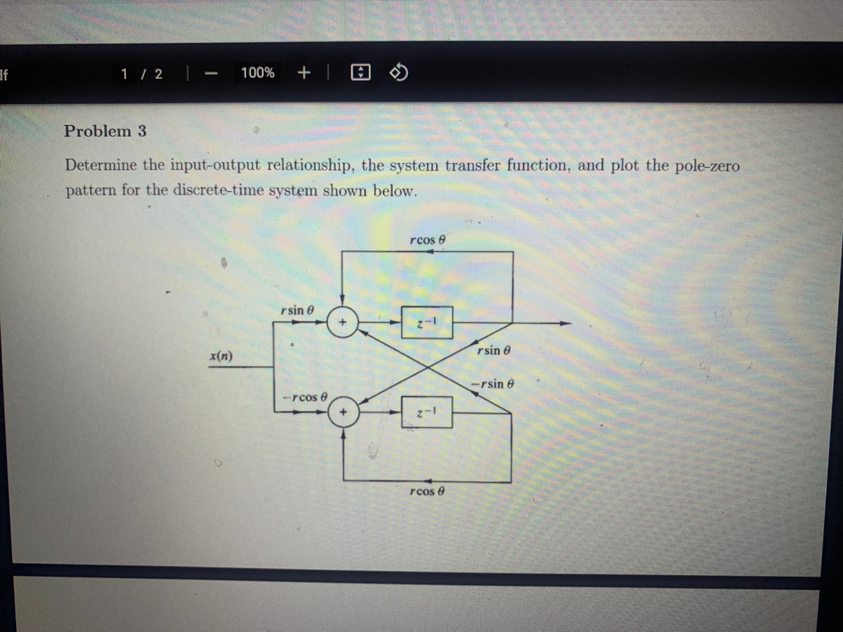

Transcribed Image Text:**Problem 3**
**Task:** Determine the input-output relationship, the system transfer function, and plot the pole-zero pattern for the discrete-time system shown below.
**Diagram Explanation:**
The system is represented using a flow diagram with the following components:
1. **Input:** The input to the system is denoted as \(x(n)\).
2. **Adders:**
- There are two adders (+) that combine incoming signals.
3. **Branches and Coefficients:**
- Four branches originating from or leading to the adders have coefficients \(r \cos \theta\) and \(-r \cos \theta\), affecting the horizontal paths, and \(r \sin \theta\) and \(-r \sin \theta\), affecting the vertical paths.
4. **Delay Elements:**
- Two sections with delay elements (\(z^{-1}\)) store and delay the signals by one time step.
5. **Output:** The overall system output is shown in the rightmost part of the diagram after signal processing.
**Function of the System:**
- The system processes the input \(x(n)\) through a specific configuration of adders, coefficients, and delay elements to produce the output. The coefficients \(r \cos \theta\) and \(r \sin \theta\) suggest a potential transformation involving trigonometric components.
This setup is often used in signal processing to model or manipulate signals with specific frequency characteristics or to implement filters. The task involves calculating the exact transfer function to understand the system’s behavior fully.
Expert Solution
This question has been solved!
Explore an expertly crafted, step-by-step solution for a thorough understanding of key concepts.

This is a popular solution

Trending nowThis is a popular solution!

Step by stepSolved in 2 steps with 5 images

Knowledge Booster


Learn more about
Need a deep-dive on the concept behind this application? Look no further. Learn more about this topic, electrical-engineering and related others by exploring similar questions and additional content below.Similar questions
- Consider the source follower circuit in Figure shown below, IQ = 10 mA VTP = -2 V, Kp = 5mA/V2, RL = 680 o, and 2 = 0.01 V–1. Where Kp=1/2 k'p(W/L). (i) What configuration is this circuit? (ii) Use T Model to Determine the small-signal voltage gain (V/V¡). (iii) What is the formula for Vo? (iv) What is the formula for Vi? (v) Determine the small-signal voltage gain (V/V:). (vi) Find the output resistance Ro. V* = 5 V KL RG= 200 k2 V=-5 V wwarrow_forwardIn your own words, describe a situation in which a small differential signal is of interest and a large common-mode signal is also present.arrow_forward2) Consider the circuit given below. (Assume: K-4mA/V', Vt=-1V, A=0, (K= µCox.(W/L)) da Perform DC analysis and calculate Va. Vsg, Vs, voltages, and Ip, gm, ro values bo Draw a small-signal equivalent circuit Co Calculate Av, Rin, Rout values as shown on the schematic Also ) satwaton mode Test for Fill inthe table VG VSG O2m A Rin Vs QUin ID vo Coo 9m Ro Av Rout Rin Routarrow_forward
- Multiple-choice questions: 1. When BJTs are used in digital circuits they usually operate in the: a. active region b. breakdown region c. saturation and cutoff regions d. linear region 2. Often a common-collector will be the last stage before the load; the main function(s) of this stage is to: a. provide voltage gain b. provide phase inversion (Inverting) c. provide a high-frequency path to improve the frequency response d. buffer the voltage amplifiers from the low-resistance load and provide impedance matching for maximum power transfer 3. A decrease in base current of a C.E. amplifier causes the voltage measured between the emitter and the collector to increase. a. True b. Falsearrow_forwardA transistor amplifier circuit is biased so that the quiescent point is to the far left of the load line midpoint. What do you expect to occur when the input voltage begins to vary? O The output voltage will be distorted on the bottom because it will hit the lower limit for VCE before the input voltage arrives at its peak. The output voltage will be distorted on the top because it will hit the upper limit for VCE before the input voltage arrives at its peak. O The output voTransistor's output voltage will look like the input voltage amplified and inverted. The output voltage will be zero (flat).arrow_forwardConsider the source follower circuit in Figure shown below, IQ = 10 mA VTP = -2 V, Kp = 5mA/V2, RL = 680 n, and 2 = 0.01 V-1. Where Kp=1/2 k'p(W/L). (i) What configuration is this circuit? Use T Model to Determine the small-signal voltage gain (V/Vi). (ii) (iii) What is the formula for Vo? (iv) What is the formula for Vi? Determine the small-signal voltage gain (VVi). (v) (vi) Find the output resistance Ro. V* =5 V 200 k2 V--5 Varrow_forward
arrow_back_ios
arrow_forward_ios
Recommended textbooks for you
- Introductory Circuit Analysis (13th Edition)Electrical EngineeringISBN:9780133923605Author:Robert L. BoylestadPublisher:PEARSON
 Delmar's Standard Textbook Of ElectricityElectrical EngineeringISBN:9781337900348Author:Stephen L. HermanPublisher:Cengage Learning
 Programmable Logic ControllersElectrical EngineeringISBN:9780073373843Author:Frank D. PetruzellaPublisher:McGraw-Hill Education
  Fundamentals of Electric CircuitsElectrical EngineeringISBN:9780078028229Author:Charles K Alexander, Matthew SadikuPublisher:McGraw-Hill Education
 Electric Circuits. (11th Edition)Electrical EngineeringISBN:9780134746968Author:James W. Nilsson, Susan RiedelPublisher:PEARSON
 Engineering ElectromagneticsElectrical EngineeringISBN:9780078028151Author:Hayt, William H. (william Hart), Jr, BUCK, John A.Publisher:Mcgraw-hill Education,
Introductory Circuit Analysis (13th Edition)
Electrical Engineering
ISBN:9780133923605
Author:Robert L. Boylestad
Publisher:PEARSON
Delmar's Standard Textbook Of Electricity
Electrical Engineering
ISBN:9781337900348
Author:Stephen L. Herman
Publisher:Cengage Learning
Programmable Logic Controllers
Electrical Engineering
ISBN:9780073373843
Author:Frank D. Petruzella
Publisher:McGraw-Hill Education
Fundamentals of Electric Circuits
Electrical Engineering
ISBN:9780078028229
Author:Charles K Alexander, Matthew Sadiku
Publisher:McGraw-Hill Education
Electric Circuits. (11th Edition)
Electrical Engineering
ISBN:9780134746968
Author:James W. Nilsson, Susan Riedel
Publisher:PEARSON
Engineering Electromagnetics
Electrical Engineering
ISBN:9780078028151
Author:Hayt, William H. (william Hart), Jr, BUCK, John A.
Publisher:Mcgraw-hill Education,