
Introductory Circuit Analysis (13th Edition)
13th Edition
ISBN: 9780133923605
Author: Robert L. Boylestad
Publisher: PEARSON
expand_more
expand_more
format_list_bulleted
Related questions
Concept explainers
Question
Develop a Verilog HDL design of the circuit provided. Show your HDL code as well as the simulation results.
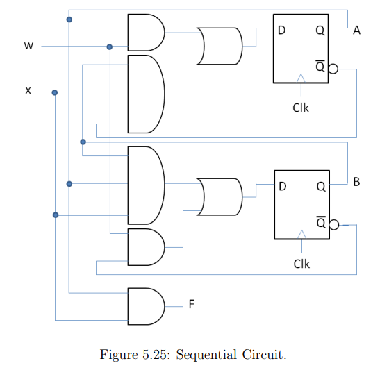

Transcribed Image Text:The diagram illustrates a sequential circuit involving logical operations, flip-flops, and input values. Below is a detailed explanation of the components and their connections:
### Components:
1. **Inputs:**
- There are two primary input signals labeled as **w** and **x**.
2. **Logic Gates:**
- The circuit contains several logic gates, including AND and OR gates.
- Each of the first two rows forms a pair of AND gates followed by an OR gate.
3. **Flip-Flops:**
- Two D flip-flops are shown, labeled as **A** and **B**.
- Each flip-flop has inputs **D** and **Clk** (clock), and outputs **Q** and **Q̅** (the inverse of Q).
4. **Output:**
- The circuit produces an output labeled **F**.
### Explanation:
- The circuit begins with inputs **w** and **x** feeding into the logic gates.
- Each pair of AND gates takes a combination of inputs and possibly outputs from the flip-flops.
- The outputs of these AND gates feed into the OR gates, whose output connects to the D input of the flip-flops (A and B).
- The clock signal (Clk) synchronizes the flip-flops, facilitating the transition of stored values.
- Logic gates also receive outputs from the flip-flops to make subsequent calculations, forming a feedback loop characteristic of sequential circuits.
- Finally, another AND gate processes input signals and outputs of flip-flops to produce the final output **F**.
This configuration demonstrates a typical synchronous sequential circuit where outputs depend not only on current inputs but also on the system's state as maintained by the flip-flops.
Expert Solution
This question has been solved!
Explore an expertly crafted, step-by-step solution for a thorough understanding of key concepts.

This is a popular solution

Trending nowThis is a popular solution!

Step by stepSolved in 2 steps with 2 images

Knowledge Booster


Learn more about
Need a deep-dive on the concept behind this application? Look no further. Learn more about this topic, electrical-engineering and related others by exploring similar questions and additional content below.Similar questions
Recommended textbooks for you
- Introductory Circuit Analysis (13th Edition)Electrical EngineeringISBN:9780133923605Author:Robert L. BoylestadPublisher:PEARSON
 Delmar's Standard Textbook Of ElectricityElectrical EngineeringISBN:9781337900348Author:Stephen L. HermanPublisher:Cengage Learning
 Programmable Logic ControllersElectrical EngineeringISBN:9780073373843Author:Frank D. PetruzellaPublisher:McGraw-Hill Education
  Fundamentals of Electric CircuitsElectrical EngineeringISBN:9780078028229Author:Charles K Alexander, Matthew SadikuPublisher:McGraw-Hill Education
 Electric Circuits. (11th Edition)Electrical EngineeringISBN:9780134746968Author:James W. Nilsson, Susan RiedelPublisher:PEARSON
 Engineering ElectromagneticsElectrical EngineeringISBN:9780078028151Author:Hayt, William H. (william Hart), Jr, BUCK, John A.Publisher:Mcgraw-hill Education,
Introductory Circuit Analysis (13th Edition)
Electrical Engineering
ISBN:9780133923605
Author:Robert L. Boylestad
Publisher:PEARSON
Delmar's Standard Textbook Of Electricity
Electrical Engineering
ISBN:9781337900348
Author:Stephen L. Herman
Publisher:Cengage Learning
Programmable Logic Controllers
Electrical Engineering
ISBN:9780073373843
Author:Frank D. Petruzella
Publisher:McGraw-Hill Education
Fundamentals of Electric Circuits
Electrical Engineering
ISBN:9780078028229
Author:Charles K Alexander, Matthew Sadiku
Publisher:McGraw-Hill Education
Electric Circuits. (11th Edition)
Electrical Engineering
ISBN:9780134746968
Author:James W. Nilsson, Susan Riedel
Publisher:PEARSON
Engineering Electromagnetics
Electrical Engineering
ISBN:9780078028151
Author:Hayt, William H. (william Hart), Jr, BUCK, John A.
Publisher:Mcgraw-hill Education,