
Introductory Circuit Analysis (13th Edition)
13th Edition
ISBN: 9780133923605
Author: Robert L. Boylestad
Publisher: PEARSON
expand_more
expand_more
format_list_bulleted
Related questions
Question
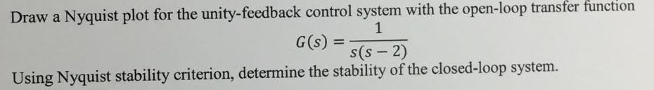

Transcribed Image Text:Draw a Nyquist plot for the unity-feedback control system with the open-loop transfer function
1
=
G(s)
s(S-2)
Using Nyquist stability criterion, determine the stability of the closed-loop system.
Expert Solution
This question has been solved!
Explore an expertly crafted, step-by-step solution for a thorough understanding of key concepts.

Step by stepSolved in 5 steps with 41 images

Knowledge Booster


Learn more about
Need a deep-dive on the concept behind this application? Look no further. Learn more about this topic, electrical-engineering and related others by exploring similar questions and additional content below.Similar questions
- Explain what is going on herearrow_forwardDesign Feedback Systems and signal flow graph(Control systems)arrow_forwardFor the feedback control system given in the figure on the right, R(s) + (a) Find the closed-loop transfer function, C(s)/R(s). (b) Determine the system's stability range for gain Kusing Routh-Hurwitz criterion. (c) What is the type of the system? (Hint: you need to convert the system to a simple unity feedback.) K 1 s(s+2)(s+5) C(s) (d) Sketch the root-locus in Matlab (hint: you need to use the open-loop transfer function with K = 1) and validate the stability region you found in (b). (e) Plot the step responses up to 10 seconds for the input of 1.5u(t) when the gain K = 22 and has the value that makes the system marginally stable on the same plane. (f) Calculate the steady-state error for the input step of 1.5u(t) for K = 22. Confirm the result with the related plot you obtained in (e). (g) Calculate the steady-state error now for an input ramp of 1.5tu(t) for K = 22 and plot this response together with the input function up to 10 seconds in order to indicate the steady-state error…arrow_forward
- solve only e,f,g and thank youarrow_forwardThe negative feedback closed-loop system was subjected to 15V. The system has a forward gain of 2 and a feedback gain of 0.5. Determine the output voltage and the error voltage.arrow_forwardHi there, I need help with this question for control systems engineering. Thank you.arrow_forward
- For a lead compensator whose zero is (-2,0) is used in a feedback control system to provide a phase lead of 45 .for desired pole location (S1=-2+3.3j), that represents the design specifications, this compensators pole is atarrow_forward8arrow_forward5.Consider the feedback system shown in figure. Determine system parameters (a, K, z, p, Ko) to guarantee closed-loop system stability. K. (s+z) K (s +p) e RO E O Y (s² – a²)arrow_forward
- Question 6 Calculate the gain margin in linear scale of a feedback control loop, when its open loop transfer function has no unstable poles and has associated the Nyquist plot si below, where a=0.71. Give your answer to 2 decimal places. Nyquist Diagram 0.6 0.4 0.2 -0.2 -0.4 -0.6 -2a/5 Real Axis -a/5 -a -4a/5 -3a/5 a/5 Calculate your answer to 2 decimal places.arrow_forwardPlease solve this problem I do not understand If my answer is true, solve it clearly please as my question is clear and plot whatever is needs.arrow_forwardFor the ideal OP-Amp in negative feedback configuration shown in Figure Q30, calculate the closed-loop gain, AvCL = VONS = (correct to 2 decimal places) Assume R1 = 10 kO, R2 = 5 kN, R3 = 2 kQ, R = 2 kN, R5 = 5 kQ, R6 = 1 kQ, RL = 10 kQ. Vs Vo R2 R R3 Rs Figure Q30.arrow_forward
arrow_back_ios
arrow_forward_ios
Recommended textbooks for you
- Introductory Circuit Analysis (13th Edition)Electrical EngineeringISBN:9780133923605Author:Robert L. BoylestadPublisher:PEARSON
 Delmar's Standard Textbook Of ElectricityElectrical EngineeringISBN:9781337900348Author:Stephen L. HermanPublisher:Cengage Learning
 Programmable Logic ControllersElectrical EngineeringISBN:9780073373843Author:Frank D. PetruzellaPublisher:McGraw-Hill Education
  Fundamentals of Electric CircuitsElectrical EngineeringISBN:9780078028229Author:Charles K Alexander, Matthew SadikuPublisher:McGraw-Hill Education
 Electric Circuits. (11th Edition)Electrical EngineeringISBN:9780134746968Author:James W. Nilsson, Susan RiedelPublisher:PEARSON
 Engineering ElectromagneticsElectrical EngineeringISBN:9780078028151Author:Hayt, William H. (william Hart), Jr, BUCK, John A.Publisher:Mcgraw-hill Education,
Introductory Circuit Analysis (13th Edition)
Electrical Engineering
ISBN:9780133923605
Author:Robert L. Boylestad
Publisher:PEARSON
Delmar's Standard Textbook Of Electricity
Electrical Engineering
ISBN:9781337900348
Author:Stephen L. Herman
Publisher:Cengage Learning
Programmable Logic Controllers
Electrical Engineering
ISBN:9780073373843
Author:Frank D. Petruzella
Publisher:McGraw-Hill Education
Fundamentals of Electric Circuits
Electrical Engineering
ISBN:9780078028229
Author:Charles K Alexander, Matthew Sadiku
Publisher:McGraw-Hill Education
Electric Circuits. (11th Edition)
Electrical Engineering
ISBN:9780134746968
Author:James W. Nilsson, Susan Riedel
Publisher:PEARSON
Engineering Electromagnetics
Electrical Engineering
ISBN:9780078028151
Author:Hayt, William H. (william Hart), Jr, BUCK, John A.
Publisher:Mcgraw-hill Education,