
Introductory Circuit Analysis (13th Edition)
13th Edition
ISBN: 9780133923605
Author: Robert L. Boylestad
Publisher: PEARSON
expand_more
expand_more
format_list_bulleted
Related questions
Concept explainers
Question
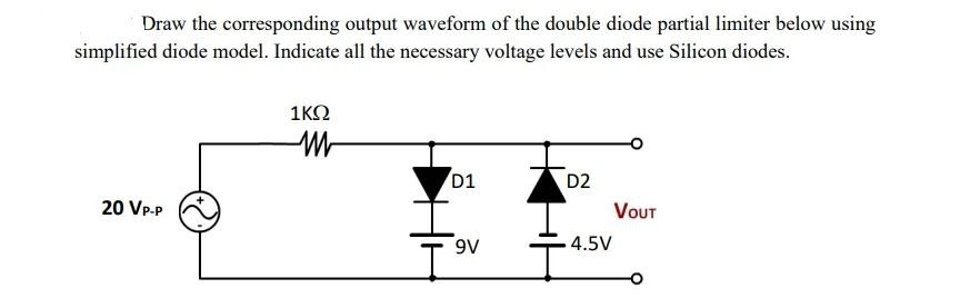

Transcribed Image Text:Draw the corresponding output waveform of the double diode partial limiter below using
simplified diode model. Indicate all the necessary voltage levels and use Silicon diodes.
20 VP-P
1KQ
M
D1
9V
D2
4.5V
VOUT
Expert Solution
This question has been solved!
Explore an expertly crafted, step-by-step solution for a thorough understanding of key concepts.

Step by stepSolved in 2 steps with 2 images

Knowledge Booster


Learn more about
Need a deep-dive on the concept behind this application? Look no further. Learn more about this topic, electrical-engineering and related others by exploring similar questions and additional content below.Similar questions
- For a pn junction diode, the temperature is 451 K. Estimate the thermal voltage in mV.arrow_forwardDraw the output waveform for the given circuit diagram with proper values and also mention the name of the circuit. The input waveform Vi is having a peak-to-peak value of 17 V and the bias voltage is 4 V. Assume diode to be silicon. Vo Maximum value of output waveform Minimum voltage of output waveformarrow_forwardPARALLEL DIODE CONFIGURATION ( NEED NEAT HANDWRITTEN SOLUTION ONLY OTHERWISE DOWNVOTE).arrow_forward
- Diode circuitsFor each circuit below, use the diode approximation with forward dropVF= 0.7 V to find the output voltage. No current flows to the output.arrow_forwardCalculate the reverse saturation current of a diode if the current at 0.2V forward bias is 0.1mA at a temperature of 25°C and the ideality factor is 1.5.arrow_forwardDetermine which diodes are forward-biased and which are reverse-biased in the configurations.. Assuming a 0.7-V drop across each forward-biased diode, determine the output voltage.arrow_forward
- Given the following circuit with VDD= 9.2 V, R=2.3 k2, then the current Iis: Use the CVD model for the diode, with VD = 0.65 V. I VDD a. 0.004000 A O b. 3.717391 A OC. 0 A d. 4.000000 A e. 0.003717 A R + VD -arrow_forwardCalculate the reverse saturation current of a diode if the current at 0.2V forward bias is 0.1mA at a temperature of 25°C and the ideality factor is 1.5.arrow_forward* When the peak output voltage is 100 V, the PIV for each diode in a center- tapped full-wave rectifier is (neglecting the diode drop) 200V O 100V 150V 55V If Vi is less than Vz. The Zener diode current is Zero Very low ********** High *< 0.5 Aarrow_forward
- 4.) In which mode will a diode generally not conduct electricity? a. Bidirectional Biased b. None of these c. Forward Biased d. Reversed Biased 5.) Consider the following schematic symbol of a semiconductor device: Which side is the Cathode? (Picture inserted down below) a. Side A b. Both side A and B c. Side B d. Neither side A or B 8.) Integrated circuits can be broken down into three basic categories. Which category does an operational amplifier (or op-amp) fall into? a. Analog b. None of these c. A combination of analog and digital d. Digitalarrow_forwardB. For the circuit shown below, assume that the zener diode has Vz-3.3V and rz=092 when reverse biased, and has a 0.7V drop when forward biased. Fill the following table for values of Vo for different values of input voltage Vi. R1 Vi Vi -8V OV 8V 1k 5V N V2 R21k Vo Voarrow_forwardDetermine the negative resistance for the tunnel diode in the figure between ?T = 0.2 ? and ?T = 0.4arrow_forward
arrow_back_ios
arrow_forward_ios
Recommended textbooks for you
- Introductory Circuit Analysis (13th Edition)Electrical EngineeringISBN:9780133923605Author:Robert L. BoylestadPublisher:PEARSON
 Delmar's Standard Textbook Of ElectricityElectrical EngineeringISBN:9781337900348Author:Stephen L. HermanPublisher:Cengage Learning
 Programmable Logic ControllersElectrical EngineeringISBN:9780073373843Author:Frank D. PetruzellaPublisher:McGraw-Hill Education
  Fundamentals of Electric CircuitsElectrical EngineeringISBN:9780078028229Author:Charles K Alexander, Matthew SadikuPublisher:McGraw-Hill Education
 Electric Circuits. (11th Edition)Electrical EngineeringISBN:9780134746968Author:James W. Nilsson, Susan RiedelPublisher:PEARSON
 Engineering ElectromagneticsElectrical EngineeringISBN:9780078028151Author:Hayt, William H. (william Hart), Jr, BUCK, John A.Publisher:Mcgraw-hill Education,
Introductory Circuit Analysis (13th Edition)
Electrical Engineering
ISBN:9780133923605
Author:Robert L. Boylestad
Publisher:PEARSON
Delmar's Standard Textbook Of Electricity
Electrical Engineering
ISBN:9781337900348
Author:Stephen L. Herman
Publisher:Cengage Learning
Programmable Logic Controllers
Electrical Engineering
ISBN:9780073373843
Author:Frank D. Petruzella
Publisher:McGraw-Hill Education
Fundamentals of Electric Circuits
Electrical Engineering
ISBN:9780078028229
Author:Charles K Alexander, Matthew Sadiku
Publisher:McGraw-Hill Education
Electric Circuits. (11th Edition)
Electrical Engineering
ISBN:9780134746968
Author:James W. Nilsson, Susan Riedel
Publisher:PEARSON
Engineering Electromagnetics
Electrical Engineering
ISBN:9780078028151
Author:Hayt, William H. (william Hart), Jr, BUCK, John A.
Publisher:Mcgraw-hill Education,