Example 25.2 provides an analysis of a real battery with internal resistance. The device attached across the terminals (see the diagram) is called the "load." The voltage across the terminals is also the voltage across out device (RL, the load.) Use the same values for the ideal battery voltage and internal resistance as in the example (12 V and 0.02 respectively.) Find voltage across the terminals, the current, and the power dissipated in the load when the load resistance is RL = 1k, much larger than the internal resistance. Report all your results to 2 significant figures. Find voltage across the terminals, the current, and the power dissipated in the load when the load resistance is 1m, much smaller than the internal resistance. Report all your results to 2 significant figures. For what ratio of RL/Rint (load over internal resistance) is the power to the load maximum? (It might help you to plot the power as a function of x = RL/Rint.)
Example 25.2 provides an analysis of a real battery with internal resistance. The device attached across the terminals (see the diagram) is called the "load." The voltage across the terminals is also the voltage across out device (RL, the load.) Use the same values for the ideal battery voltage and internal resistance as in the example (12 V and 0.02 respectively.) Find voltage across the terminals, the current, and the power dissipated in the load when the load resistance is RL = 1k, much larger than the internal resistance. Report all your results to 2 significant figures. Find voltage across the terminals, the current, and the power dissipated in the load when the load resistance is 1m, much smaller than the internal resistance. Report all your results to 2 significant figures. For what ratio of RL/Rint (load over internal resistance) is the power to the load maximum? (It might help you to plot the power as a function of x = RL/Rint.)

Chapter10: Direct-current Circuits
Section: Chapter Questions
Problem 74AP: Consider a circuit that consists of a real battery with an emf and an internal resistance of r...

Related questions

Question
Transcribed Image Text:Problem 1
Example 25.2 provides an analysis of a real battery with internal resistance. The device attached
across the terminals (see the diagram) is called the "load." The voltage across the terminals is also
the voltage across out device (RL, the load.) Use the same values for the ideal battery voltage and
internal resistance as in the example (12 V and 0.02 2 respectively.)
Find voltage across the terminals, the current, and the power dissipated in the load when the load
resistance is R₁ = 1kn, much larger than the internal resistance. Report all your results to 2
significant figures.
Find voltage across the terminals, the current, and the power dissipated in the load when the load
resistance is 1m2, much smaller than the internal resistance. Report all your results to 2 significant
figures.
For what ratio of RL/Rint (load over internal resistance) is the power to the load maximum? (It
might help you to plot the power as a function of x = RL/Rint.)
Transcribed Image Text:EXAMPLE 25.2
Internal Resistance: Starting a Car
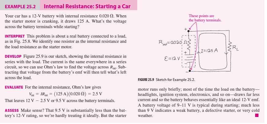
Your car has a 12-V battery with internal resistance 0.020 . When
the starter motor is cranking, it draws 125 A. What's the voltage
across the battery terminals while starting?
INTERPRET This problem is about a real battery connected to a load,
as in Fig. 25.8. We identify one resistor as the internal resistance and
the load resistance as the starter motor.
DEVELOP Figure 25.9 is our sketch, showing the internal resistance in
series with the load. The current is the same everywhere in a series
circuit, so we can use Ohm's law to find the voltage across Rint-Sub-
tracting that voltage from the battery's emf will then tell what's left
across the load.
EVALUATE For the internal resistance, Ohm's law gives
Vint= IRint = (125 A) (0.020 f2) = 2.5 V
That leaves 12 V - 2.5 V or 9.5 V across the battery terminals.
ASSESS Make sense? That 9.5 V is substantially less than the bat-
tery's 12-V rating, so we're hardly treating it ideally. But the starter
These points are
the battery terminals.
R₁0020 ns
"int"
ε = 12v!
I=125 A
_MW
FIGURE 25.9 Sketch for Example 25.2.
motor runs only briefly; most of the time the load on the battery-
headlights, ignition system, electronics, and so on-draws far less
current and so the battery behaves essentially like an ideal 12-V emf.
A battery voltage of 9-11 V is typical during starting; much less
than 9 V indicates a weak battery, a defective starter, or very cold
weather.
Expert Solution
This question has been solved!
Explore an expertly crafted, step-by-step solution for a thorough understanding of key concepts.

This is a popular solution!

Trending now
This is a popular solution!

Step by step
Solved in 5 steps with 8 images

Knowledge Booster


Learn more about
Need a deep-dive on the concept behind this application? Look no further. Learn more about this topic, physics and related others by exploring similar questions and additional content below.Recommended textbooks for you