Figure 10.24 The circuit for Examples 10.10 and 10.11. 3000 0 j4000 N RL 10/0° (+ V(rms) b Figure 10.24 Full Alternative Text HE
Figure 10.24 The circuit for Examples 10.10 and 10.11. 3000 0 j4000 N RL 10/0° (+ V(rms) b Figure 10.24 Full Alternative Text HE

Power System Analysis and Design (MindTap Course List)
6th Edition
ISBN:9781305632134
Author:J. Duncan Glover, Thomas Overbye, Mulukutla S. Sarma
Publisher:J. Duncan Glover, Thomas Overbye, Mulukutla S. Sarma
Chapter2: Fundamentals
Section: Chapter Questions
Problem 2.2MCQ: If the rms phasor of a voltage is given by V=12060 volts, then the corresponding v(t) is given by...

Related questions

Question
A load impedance having a constant phase angle of −36.87° is connected
across the terminals a and b in the circuit shown. The magnitude
of ZL is varied until the average power delivered is maximized under the
given restriction.
1. Specify ZL in rectangular form.
2. Calculate the average power delivered to ZL.
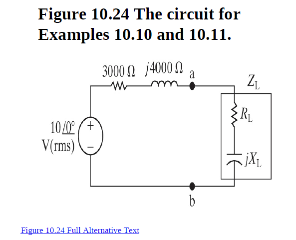
Transcribed Image Text:Figure 10.24 The circuit for
Examples 10.10 and 10.11.
3000 0 j4000 N
RL
10/0° (+
V(rms)
b
Figure 10.24 Full Alternative Text
HE
Expert Solution
This question has been solved!
Explore an expertly crafted, step-by-step solution for a thorough understanding of key concepts.

This is a popular solution!

Trending now
This is a popular solution!

Step by step
Solved in 2 steps with 2 images

Knowledge Booster


Learn more about
Need a deep-dive on the concept behind this application? Look no further. Learn more about this topic, electrical-engineering and related others by exploring similar questions and additional content below.Recommended textbooks for you
Power System Analysis and Design (MindTap Course …
Electrical Engineering
ISBN:
9781305632134
Author:
J. Duncan Glover, Thomas Overbye, Mulukutla S. Sarma
Publisher:
Cengage Learning
Power System Analysis and Design (MindTap Course …
Electrical Engineering
ISBN:
9781305632134
Author:
J. Duncan Glover, Thomas Overbye, Mulukutla S. Sarma
Publisher:
Cengage Learning