Q1. Two loads Z, 10 + j20 N , Z2 100 – j270, N are connected across a Vs=400Vrms, 50 Hz, source as shown in fig. 1. a) Find the total real power, the reactive power and the power factor at the source, and the total current in uncompensated case (i.e. when no compensation capacitor C is connected to the loads). b) Find the capacitance of the shunt compensation capacitor C to be connected across the loads to improve the overall power factor to 0.866 lagging. 12 R1 10 Ohm R2 Vs 100 Ohm C2 - j270 Ohm L1 +j20 Ohm fig.1
Q1. Two loads Z, 10 + j20 N , Z2 100 – j270, N are connected across a Vs=400Vrms, 50 Hz, source as shown in fig. 1. a) Find the total real power, the reactive power and the power factor at the source, and the total current in uncompensated case (i.e. when no compensation capacitor C is connected to the loads). b) Find the capacitance of the shunt compensation capacitor C to be connected across the loads to improve the overall power factor to 0.866 lagging. 12 R1 10 Ohm R2 Vs 100 Ohm C2 - j270 Ohm L1 +j20 Ohm fig.1

Power System Analysis and Design (MindTap Course List)
6th Edition
ISBN:9781305632134
Author:J. Duncan Glover, Thomas Overbye, Mulukutla S. Sarma
Publisher:J. Duncan Glover, Thomas Overbye, Mulukutla S. Sarma
Chapter2: Fundamentals
Section: Chapter Questions
Problem 2.17P: Consider a load impedance of Z=jwL connected to a voltage and V let the current drawn be I. (a)...

Related questions
Question
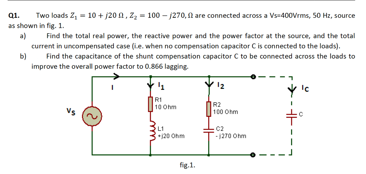
Transcribed Image Text:Q1.
Two loads Z,
10 + j20 N, Z2 = 100 – j270, N are connected across a Vs=400Vrms, 50 Hz, source
as shown in fig. 1.
a)
Find the total real power, the reactive power and the power factor at the source, and the total
current in uncompensated case (i.e. when no compensation capacitor C is connected to the loads).
b)
Find the capacitance of the shunt compensation capacitor C to be connected across the loads to
improve the overall power factor to 0.866 lagging.
12
Ic
R1
R2
10 Ohm
Vs
100 Ohm
C2
- j270 Ohm
L1
+j20 Ohm
fig.1.
- - -
Expert Solution
This question has been solved!
Explore an expertly crafted, step-by-step solution for a thorough understanding of key concepts.

This is a popular solution!

Trending now
This is a popular solution!

Step by step
Solved in 5 steps with 2 images

Knowledge Booster


Learn more about
Need a deep-dive on the concept behind this application? Look no further. Learn more about this topic, electrical-engineering and related others by exploring similar questions and additional content below.Recommended textbooks for you
Power System Analysis and Design (MindTap Course …
Electrical Engineering
ISBN:
9781305632134
Author:
J. Duncan Glover, Thomas Overbye, Mulukutla S. Sarma
Publisher:
Cengage Learning
Power System Analysis and Design (MindTap Course …
Electrical Engineering
ISBN:
9781305632134
Author:
J. Duncan Glover, Thomas Overbye, Mulukutla S. Sarma
Publisher:
Cengage Learning