Figure Q4a shows a basic current mirror structure (in its 'sink' form) which is designed to provide the current Ir at its output Io by operating transistors T1 and T2 identically : Question 4 VDD IR T3 TI T2 TI T2 OV OV Figure Q4a : Current Mirror Figure Q4b : Widlaw Mirror Show that the current relationship of the circuit in figure Q4a is ( where Ic = BIb for both transistors and T1 and T2 are matched) : IR 1+ b) If the two transistors in figure Q4a are not matched in terms of their Vbe's compensation can be provided by placing a resistor 'R' in one of the emitter legs of the transistors. Assuming Vbez > Vbel by 0.05V and IR = Io = 10mA sketch an appropriate structure and value for R. c) Describe how the 'offset' compensation referred to in Q4b occurs in practice for a 741 op-amp ? (p Sketch the 'Source' form of figure Q4a e) Figure Q4b shows the buffered Widlar mirror. Briefly describe how the addition of transistor T3 improves operation.
Figure Q4a shows a basic current mirror structure (in its 'sink' form) which is designed to provide the current Ir at its output Io by operating transistors T1 and T2 identically : Question 4 VDD IR T3 TI T2 TI T2 OV OV Figure Q4a : Current Mirror Figure Q4b : Widlaw Mirror Show that the current relationship of the circuit in figure Q4a is ( where Ic = BIb for both transistors and T1 and T2 are matched) : IR 1+ b) If the two transistors in figure Q4a are not matched in terms of their Vbe's compensation can be provided by placing a resistor 'R' in one of the emitter legs of the transistors. Assuming Vbez > Vbel by 0.05V and IR = Io = 10mA sketch an appropriate structure and value for R. c) Describe how the 'offset' compensation referred to in Q4b occurs in practice for a 741 op-amp ? (p Sketch the 'Source' form of figure Q4a e) Figure Q4b shows the buffered Widlar mirror. Briefly describe how the addition of transistor T3 improves operation.

Delmar's Standard Textbook Of Electricity
7th Edition
ISBN:9781337900348
Author:Stephen L. Herman
Publisher:Stephen L. Herman
Chapter18: Resistive-inductive Parallel Circuits
Section: Chapter Questions
Problem 8PP: In an R-L parallel circuit, ET=48 volts, IT=0.25 amps, R=320. Find XL.

Related questions

Question
Transcribed Image Text:Question 4
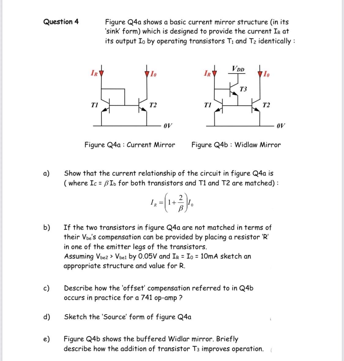
Figure Q4a shows a basic current mirror structure (in its
'sink' form) which is designed to provide the current Ir at
its output Io by operating transistors Ti and T2 identically :
VDD
IR
IR
T3
T1
T2
T1
T2
OV
OV
Figure Q4a : Current Mirror
Figure Q4b : Widlaw Mirror
a)
Show that the current relationship of the circuit in figure Q4a is
( where Ic = BIb for both transistors and T1 and T2 are matched) :
IR
2
=|1+
If the two transistors in figure Q4a are not matched in terms of
b)
their Vbe's compensation can be provided by placing a resistor 'R'
in one of the emitter legs of the transistors.
Assuming Vbez > Vbel by 0.05V and Ir = Io = 10mA sketch an
appropriate structure and value for R.
c)
Describe how the 'offset' compensation referred to in Q4b
occurs in practice for a 741 op-amp ?
d)
Sketch the 'Source' form of figure Q4a
e)
Figure Q4b shows the buffered Widlar mirror. Briefly
describe how the addition of transistor T3 improves operation.
Expert Solution
This question has been solved!
Explore an expertly crafted, step-by-step solution for a thorough understanding of key concepts.

This is a popular solution!

Trending now
This is a popular solution!

Step by step
Solved in 2 steps

Knowledge Booster


Learn more about
Need a deep-dive on the concept behind this application? Look no further. Learn more about this topic, electrical-engineering and related others by exploring similar questions and additional content below.Recommended textbooks for you
Delmar's Standard Textbook Of Electricity
Electrical Engineering
ISBN:
9781337900348
Author:
Stephen L. Herman
Publisher:
Cengage Learning
Delmar's Standard Textbook Of Electricity
Electrical Engineering
ISBN:
9781337900348
Author:
Stephen L. Herman
Publisher:
Cengage Learning