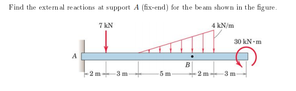
Find the external reactions at support A (fix-end) for the beam shown in the figure. 7 kN 4 kN/m 30 kN •m A 2 m 3 m 5 m 2 m 3 m-


Q: Problem C-3 [Beam Bending - Normal Stress] A simply supported beam (i.e., with a pin support at…
A:
Q: Anchor of the beam given in the figure is built-in support, B point is movable support and G joint.…
A: Let the reactions at fixed support 'A' be: RAH , RAV , MA. Let the reactions at pin joint 'G' be:…
Q: For the beam in the figure that has as data: P = 24 kN, w = 12 kN /m and L = 8 m, El = cte. Applying…
A: According to the given details in the question. P = 24kN , E = 200 GPa = 200x106 kN/m2 , I = 5x10⁸…
Q: Cantilever beam is loaded as shown in the figure above. a. Determine the Moment at point O b.…
A:
Q: A simply supported beam which has 16 mm height and 8 mm thickness is supported by pin at A and…
A:
Q: Find the support reactions of the beam given in the figure.
A:
Q: Calculate the internal reactions for the member along section M-M shown in the Figure. 6 lb/ft 9 ft…
A: Since the end A is knife edge supported thus there will be two support reactions i.e. one in…
Q: For the beam shown, determine the support reactions using singularity functions and procedure 1 from…
A: he support reactions using singularity functions
Q: span 5 m is loaded as shown in Figure, Using the principle of virtual work, find the reactions at A…
A:
Q: H.W. 3 / Find the reactions of the simply supported beam shown in Figure below 200 lb 400 lb-ft A |B…
A: Given RAy=200 lb
Q: Sample Problem: Determine the reactions for the beam loaded as shown in the figure below. 12 KN 15…
A:
Q: The cantilever beam AB shown in the figurehas an extension BCD attached to its free end.A force P…
A:
Q: 60 kN/m 20 N 30 kN 10 kN/m
A:
Q: 3 The ratio of the reactions RA and RB of a simply supported beam shown in * below figure is 5 kN…
A:
Q: Anchor point of the beam given in the figure is fixed support and B point is movable support. Find…
A:
Q: In figure, there is a single rigid beam supported at two points: A and B. 250 N 2 m Calculate the…
A:
Q: Segments AB and BC of beam ABC are pin connected a small distance to the right of joint B (sec…
A: Mechanics Of Material
Q: A simply supported beam AB supports a trapezoid ally distributed load (see figure). The intensity of…
A: →First calculating Reactions:∑MB=0⇒RA(4)−25(4)42−25×42×2×43=0⇒RA=83.33kN+↑…
Q: Consider the circular bent rod with diameter 20 mm. The free-end of the bend is subjected to loads…
A:
Q: Q/ For the beam shown in the figure below, find deflection and rotation at point B. EI=12000 kN.m2.…
A:
Q: Figure Y shows a rigid body consisting of beam ABC loaded with a 500 Nm moment, a box with a weight…
A: Given Data, Moment, M = 500 Nm(clockwise) Weight of the box,W = 600 N Mass of the tyre, m= 10 Kg To…
Q: Calculate the support reaction at A and B for the beam shown in the figure below. Take F= 570 N.
A: Given: F=570 N To determine: Reaction forces
Q: The homogeneous beam shown in the figure is suspended by a cable at point B and is pin supported at…
A:
Q: There is an inclined beam with pin and roller supports at B and A, respectively. The vertical…
A: Convert Uniformly varying load into point load and draw free body diagram of beam.
Q: H.W. 1 / Find the reactions of the simply supported beam shown in Figure below 6 kN/m 20 kN A B Fig.…
A:
Q: Figure below shows a simply supported uniform beam supports a 40 kN load. Determine the reactions R.…
A: for solution refer below images.
Q: 11.3-6 A horizontal beam AB is pin-supported at end A and carries a clockwise moment M at joint B,…
A:
Q: The homogeneous beam shown in the figure is suspended by a cable at point B and is pin supported at…
A:
Q: For the beam shown in the figure if W- 14 KN/m. Determine the following: 14. The normal force at…
A: (14)
Q: A G Support reactions will be found in the gerber beam whose loading condition is given in the…
A:
Q: 2: For the beam shown in Fig.(2), find the reaction forces at supports A and B respectively? %) 20…
A:
Q: :for the figure shown below, calculate the reactions at the point O 30° 15 kN-m 3 kN A B 1.4 kN F1.2…
A:
Q: Specily where th (c) Find the support reactions at A and C (As shown in the figure, A is a pin…
A:
Q: Segments AB and BC of beam ABC arepin connected a small distance tothe right ofjoint B (sec figure).…
A: Strength Of Material
Q: 30 kN/m 10 kN 10 kN/m 3.5 m60 B 225 kN-m 30 kN/m |2.5 m- 6 m 9 m
A:
Q: Find the external reactions at supports A (hinge) and B (roller) for the beam shown in the figure.…
A: To find: The external reaction supports A and B. FBD: The free body diagram shown below:
Q: 6 kN/m +x 18 kN-m A B D 3.0 m- 3.0 m- 4.0 m An l-section Beam ABCD is pin supported at points B and…
A: For solution refer below images.
Q: Calculate the vertical reaction force at A (kN). The cantilever beam and loading are shown in…
A:
Q: Figure 3 represents a cantilever beam A, B, C, D, E clamped at point E and carrying various types of…
A: Cantilever beam A cantilever beam is a member with one end projecting beyond the point of support,…
Q: 30 cm 40 cm 70 cm to 60 cm 15 cm E 250 kg 35 cm 30 cm- A 250 kg load is supported by a frame as…
A:
Q: A B Fuztuzt -L/2- -L/2- L/2 - Find deflection in the middle part of the EU on the beam in the…
A: Let us consider a dummy load P at the mid of beam i.e 3L/4 distance from both the ends. The free…
Q: Q1: For structure shown in Figure, Find the reactions of the hinge force at A, B, and C. 2 m 200 N/m…
A:
Q: 11.3-6 A horizontal beam AB is pin-supported at end A and carries a clockwise moment M at joint B,…
A:
Q: B 1.5 0.5 0.5 (14 kN) (s0 kN)
A:
Q: Example: Determine the reactions at supports (A) and (B) for the beam loaded as shown in figure…
A: Given: Support reaction at point A is RA and Support reaction at point B is RBH, RBV. F = 73+30 =…
Q: H.W. 4 / Find the reactions of the simply supported beam shown in Figure below 50 kN 30 KN/m Int.…
A: As per our guideline we suppose to answer only one question. Kindly repost other questions as a…
Q: A beam (AB) is attached to a roller at A and a pin at B. It is subjected to three concentrated…
A:
Q: H.W. 4 / Find the reactions of the simply supported beam shown in Figure below 50 kN 30 kN/m Int.…
A:
Q: . A homogeneous rod of constant cross section is attached to unyielding supports. It carries an…
A:
Q: 8.4-10 An overhanging beam ABC has a guided support at A, a rectangular cross section, and sup-…
A: We have to determine the above question


Step by step
Solved in 2 steps


- A C 200 x 17.1 channel section has an angle with equal legs attached as shown; the angle serves as a lintel beam. The combined steel section is subjected to a bending moment M having its vector directed along the z axis, as shown in the figure. The cent roi d C of the combined section is located at distances xtand ycfrom the centroid (C1) of the channel alone. Principal axes yl and yvare also shown in the figure and properties Ix1,Iy1and 0pare given. Find the orientation of the neutral axis and calculate the maximum tensile stress exand maximum compressive stress if the angle is an L 76 x 76 x 6.4 section and M = 3.5 kN - m. Use the following properties for principal axes for the combined section:/^, = 18.49 X 10⁶ nrai4,/;| = 1.602 X 106 mm4, ep= 7.448*(CW),_r£ = 10.70 mm,andvf= 24.07 mm.Two flat beams AB and CD, lying in horizontal planes, cross at right angles and jointly support a vertical load P at their midpoints (see figure). Before the load P is applied, the beams just touch each other. Both beams are made of the same material and have the same widths. Also, the ends of both beams are simply supported. The lengths of beams AB and CD are LABand LCD, respectively. What should be the ratio tABltCDof the thicknesses of the beams if all four reactions arc to be the same?During construction of a highway bridge, the main girders are cantilevered outward from one pier toward the next (see figure). Each girder has a cantilever length of 48 m and an I-shaped cross section with dimensions shown in the figure. The load on each girder (during construction) is assumed to be 9,5 kN/m, which includes the weight of the girder. Determine the maximum bending stress in a girder due to this load.
- A temporary wood flume serving as a channel for irrigation water is shown in the figure. The vertical boards forming the sides of the flume are sunk in the ground, which provides a fixed support. The top of the flume is held by tic rods that are tightened so that there is no deflection of the boards at that point. Thus, the vertical boards may be modeled as a beam AB, supported and loaded as shown in the last part of the figure. Assuming that the thickness t of the boards is 1,5 in., the depth d of the water is 40 in., and the height h to the tie rods is 50 in., what is the maximum bending stress in the boards? Hint: The numerically largest bending moment occurs at the fixed support.-10 The simple beam AB shown in the figure supports two equal concentrated loads P: one acting downward and the other upward. Determine the angle of rotation A at the left-hand end, the deflection 1under the downward load, and the deflection 2 at the midpoint of the beam.A beam supporting a uniform load of intensity q throughout its length rests on pistons at points A, C and B (sec figure). The cylinders are filled with oil and are connected by a tube so that the oil pressure on each piston is the same. The pistons at A and B have diameter d1and the piston at C has diameter D2. (a) Determine the ratio of d2to d1so that the largest bending moment in the beam is as small as possible. Under these optimum conditions, what is the largest bending moment Mmaxin the beam? What is the difference in elevation between point C and the end supports?
- The cantilever beam AB shown in the figure has an extension BCD attached to its free end. A force P acts at the end of the extension. Find the ratio aiL so that the vertical deflection of point B will be zero. Find the ratio aiL so that the angle of rotation at point B will be zero.The cross section of a bimetallic strip is shown in the figure. Assuming that the moduli of elasticity for metals A and B are EA=168 GPa and EB= 90 GPa, respectively, determine the smaller of the two section moduli for the beam. (Recall that section modulus is equal to bending moment divided by maximum bending stress.) In which material does the maximum stress occur?A propped cantilever beam with a length L = 4 m is subjected to a trapezoidal load with intensities q0= 10 kN/m and q1 = 15 kN/m. Find the reactions at A and B. Hint: The loading is the sum of uniform and triangular loads.
- Uniform load q = 10 lb/ft acts over part of the span of fixed-end beam AB (see figure). Upward load P = 250 lb is applied 9 ft to the right of joint A. Find the reactions at A and B.A cylindrical brick chimney of height H weighs w = 825 lb/ft of height (see figure). The inner and outer diameters are d1= 3 ft and d2= 4 ft, respectively. The wind pressure against the side of the chimney is p = 10 lb/ft2 of projected area. Determine the maximum height H if there is to be no tension in the brickwork.A flying but tress transmit s a load P = 25 kN, acting at an angle of 60º to the horizontal, to the top of a vertical buttress AB (see figure). The vertical buttress has height h = 5.0 m and rectangular cross section of thickness t = 1.5 m and width b = 1.0 m (perpendicular to the plane of the figure). The stone used in the construction weighs y = 26 kN/m3. What is the required weight W of the pedestal and statue above the vertical buttress (that is, above section A) to avoid any tensile stresses in the vertical buttress?