Find the rod forces in the truss system, whose dimensions and loading condition are given in the figure. (El = constant) please it needs to be resolved within 1 hour
Find the rod forces in the truss system, whose dimensions and loading condition are given in the figure. (El = constant) please it needs to be resolved within 1 hour

Mechanics of Materials (MindTap Course List)
9th Edition
ISBN:9781337093347
Author:Barry J. Goodno, James M. Gere
Publisher:Barry J. Goodno, James M. Gere
Chapter2: Axially Loaded Members
Section: Chapter Questions
Problem 2.2.1P: A 10-ft rigid bar AB is supported with a vertical translational spring at A and a pin at B. The bar...

Related questions
Question
Solve it correctly.
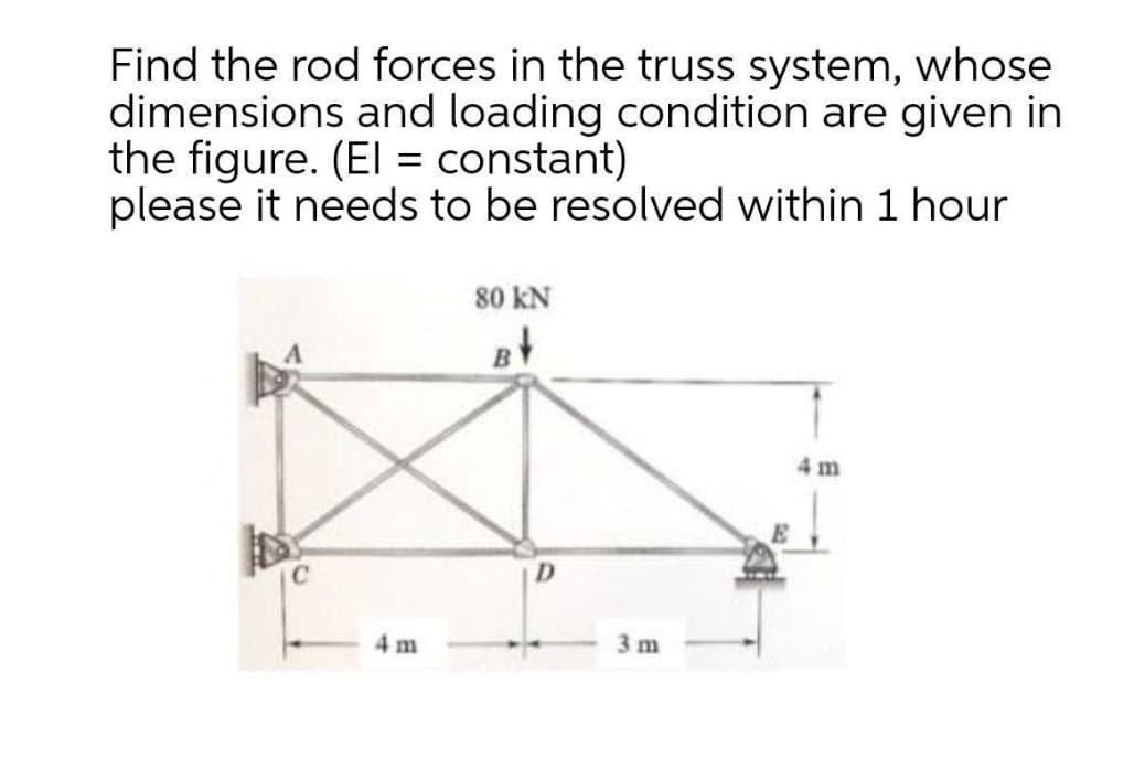
Transcribed Image Text:Find the rod forces in the truss system, whose
dimensions and loading condition are given in
the figure. (El = constant)
please it needs to be resolved within 1 hour
80 kN
4 m
D.
4 m
3 m
Expert Solution
This question has been solved!
Explore an expertly crafted, step-by-step solution for a thorough understanding of key concepts.

Step by step
Solved in 2 steps with 2 images

Knowledge Booster


Learn more about
Need a deep-dive on the concept behind this application? Look no further. Learn more about this topic, mechanical-engineering and related others by exploring similar questions and additional content below.Recommended textbooks for you
Mechanics of Materials (MindTap Course List)
Mechanical Engineering
ISBN:
9781337093347
Author:
Barry J. Goodno, James M. Gere
Publisher:
Cengage Learning
Mechanics of Materials (MindTap Course List)
Mechanical Engineering
ISBN:
9781337093347
Author:
Barry J. Goodno, James M. Gere
Publisher:
Cengage Learning