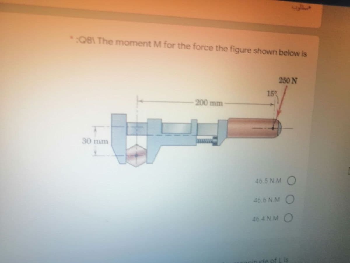
:Q81 The moment M for the force the figure shown below is 250 N 15 200 mm 30 mm 46.5 N.MO


Q: A distributed force and a concentrated force act on the 20m long bar shown below. 2 kN 400 N/m A B *…
A:
Q: A bar with a right angle bend is supported by a collar A on smooth square rod, and by a roller at B.…
A:
Q: A free body diagram of a section of a beam is shown. The reaction force (RA) is 38 kN. What is the…
A:
Q: 100 kN 1.5 10 kN/m 1.5
A: given:
Q: 3. The roller at point C in the figure below can only support a force of 55 O N. If the force P is…
A:
Q: MAKE A FREE BODY DIAGRAM Síx forces are acting on the mesh as shown in the figure below. Find the…
A:
Q: 3:-An IC engine have a bore of 80 mm and crank radius 50 mm 10.27 and a P-V diagram as shown beside,…
A: The IC engine is a heat engine in which the air-fuel combination is burned inside the combustion…
Q: Q. 60. The figure shows a schematic layout of a hydraulic jack. The load to be raised weighs 20,000…
A:
Q: 3m 3m A MN kN 2m I 3m 1.5m 6m E In the above figure, thick red lines indicated as cables. If there…
A: Draw the free body diagram.
Q: solve the following for forces and displacement at each of the nodes. where F is 500lb. M is 70…
A:
Q: Draw the axial force, shear force and bending moment diagram for the frame shown in Fig. below. S KN…
A:
Q: A beam with rigid support at A, pin connection at C and roller at D has the geometry and loads as…
A:
Q: A seismic portal frame is shown in the figure below. The structure is used as an essential facility…
A: Given:-F1=3000 kNF2=2000 kNTo find:-Maximum moment and beam analysis
Q: Problem#3. A chord in a bridge truss is composed of the elements as shown ; 18 x 1" Size Area Units…
A: HERE now we have to find out the centroidal moment of the inertia
Q: The cantilever truss in the figure is hinged at D and E. Find the force in member BD. 1000 1b 60 60…
A:
Q: The figure shows a kettle bell with a mass of 15kg suspended by three cables. Using the tabulated…
A:
Q: A sandwich board advertising sign is constructed as shown in the figure below. Hinge- 0.50m Chain…
A: A hinge or pin support will exert both horizontal and vertical components of reaction as the…
Q: 2. a) Compute the resultant force for the loads shown in Figure 1 acting on the cantilever. What…
A: A pin support will exert both horizontal and vertical components of reaction as the reaction forces.…
Q: * For figure below, the tension in the cable is 0.25 m 25° B 0.5 m 0.12 m 1.5 m 14 *N - 5 m - 23.5 O…
A: The free-body diagram of the beam is shown below. Here, T denotes the tension in the cable.
Q: Find the Shear Moment Diagram of the following problems using ONLY AREA METHOD. 30 kN 50 kN to B A…
A: 2. Equate the net vertical force on the beam to zero for the static equilibrium of the beam. ∑Fy=0…
Q: The L-shaped arm ABC shown in the Fig.3 lies in a vertical plane and pivots about a horizontal pin…
A:
Q: 800 N-m 2 m .8 m 3 m .4 m .2 m Figure P.5.29. 5.30. Find the supporting force systems at A and B.…
A: Since you have asked multiple questions, only the first question is solved for you. If you want any…
Q: The cantilever truss in the figure is hinged at D and E. Find the force in member CE. 1000 Ib 60 60°…
A:
Q: A vertical pole consisting of a circular tubeof outer diameter 5 in. and inner diameter 4.5 in.…
A: Introduction: When external loads are applied to a beam, they must be limited in order to maintain…
Q: P- 55 N 16 m 45 16m Figure 1(0) The 55 N force P is applied at point C, perpendicular to the portion…
A:
Q: 1. A beam of length L is simply supported shown as follows. A concentrated force F is applied at…
A:
Q: T 53.0°
A:
Q: 4. Give practical applications of wire ropes. What are the advantages of wire ropes? 5. What is the…
A: Hello. Since you have posted multiple questions and not specified which question needs to be solved,…
Q: Determine the maximum shear force in kN in the figure below. 2 kN/m B A C 5 kN 4 m 2 m O -10 O 10 O…
A:
Q: Draw Shear Force and Bending Moment Diagram Graphically for the following Вeam. P=20KN q=5kN/m A, ¡B…
A:
Q: A mechanism carries a constant load P applied to the seat as E shown. Calculate the forces, in…
A: Forces in mechanisms can be calculated by balancing them in particular directions. The sum of all…
Q: The cantilever truss in the figure is hinged at D and E. Find the force in member BC. 1000 1b 60 60°…
A:
Q: A person with mass 55.0 kg stands d = 2.40 m away from the wall on a x = 6.10 m beam, as shown in…
A: Given:- d=2.40m x=6.10m Mass of person(M1)=55kg Mass of beam(M2)=40kg Angle=30 degree To find:…
Q: The cantilever truss in the figure is hinged at D and E. Find the force in member AB. 1000 Ib 60 60…
A:
Q: Lets consider a simple supported beam subjected to a triangular distributed load and a couple moment…
A:
Q: For the system shown in Figure, Maximum shear force is:* 50KN 2kN/m A C 1m 4m
A:
Q: 8 m -5m 4 m 5 m 5 m 15 m 500 N In connection with the above figure, as an Engineer you have to…
A:
Q: Problem 2. Each segment of bar ABC has length Z. and shear modulus G and both segments have solid…
A:
Q: The cantilever truss in the figure is hinged at D and E. Find the force in member BD. 1000 1b 60°…
A: As per given question We have to determine all forces members including BD
Q: Problem 2 The resultant of three parallel loads (one is missing in Fig. P-2) is 13.6 kg acting up at…
A:
Q: Find the Tensions TCA and TCB for the system as shown in figure. Take R = 200 mm, S= 240 mm 0 = 55°,…
A: Given: The weight is W = 14 kN, The dimension R =200 mm, The dimension S =240 mm, The angle θ=55°.
Q: Q.2) A brass bar 500 mm long and 100 mm × 100 mm in cross-section is subjected to an axial pull in…
A: L=500 mm A=100 ×100 mm2μ=.25 E=100 Gpa ∆v=50 mm3 ∆vvi=1-2μσx∆vvi=1-2μ×PAE∆vA×L=1-2μ×PAEP=∆v×E1-2μ×L…
Q: A countershaft carrying two V-belt pulleys Is shown In the figure. Pulley A recelves power from a…
A:
Q: 13)The Beam in figure below is weightless. A moveable weight(mass)W of 300 lbm is to be attached as…
A: As per our guidelines, we are supposed to answer only first three subparts in case of multiple…
Q: Given the loading criteria in the figure below, find all reaction forces. |80 kN 30 kN/m 2m 3m 2m
A: A uniformly distributed load (UDL) is a load that is evenly distributed throughout the whole…
Q: 4/ For the figure below the spring is used to stop a 10 package. If the maximum deflection in the…
A:
Q: For the cables shown in the figure, find the forces in each cable if cable C pass over a pulley and…
A: The weight of the holding mass is as follows: W=mgW=10×9.81W=98.1 N The tension in the cable D will…
Q: Problem 2. Each segment of bar ABC has length Z. and shear modulus G and both segments have solid…
A:
Q: For the given figure below, the beam is 57.4 m long. It has a rectangular cross-section area with…
A: Consider the diagram as shown below for the given beam. Here Fs is the spring force.


Step by step
Solved in 2 steps with 2 images


- Solve the preceding problem (W 250 × 44.8) if the resultant force P equals 110 kN and E = 200 GPa.Repeat Problem 11.3-9. Use two C 150 × 12.2 steel shapes and assume that E = 205 GPa and L = 6 m.A large precast concrete panel for a warehouse is raised using two sets of cables at two lift lines, as shown in the figure part a. Cable 1 has a length L1 = 22 Ft, cable 2 has a length L2= 10 ft, and the distance along the panel between lift points Band D is d = 14 ft (see figure part b). The total weight of the panel is W = 85 kips. Assuming the cable lift Forces F at each lift line are about equal, use the simplified model of one half of the panel in figure part b to perform your analysis for the lift position shown. Find the required cross-sectional area AC of the cable if its breaking stress is 91 ksi and a factor of safety of 4 with respect to failure is desired.
- A spray nozzle for a garden hose requires under a water pressure force fp= 30 lb at C (see figure a force F = 5 lb to open the spring-loaded spray part c). Use dimensions given in figure part a chamber AB. The nozzle hand grip pivots about a (a) Find the force in the pin at O due to applied force F pin through a flange at O. Each of the two flanges force F has a thickness t = 1/16 in., and the pin has a diam- (b) Find average shear stress taver and bearing stress eter dp = 1/8 in. (see figure part a). The spray nozzle is attached to the garden hose with a quick release fitting at B (see figure part b). Three brass balls Find the average shear stress Ta,„ in the brass (diameter db= 3/16 in.) hold the spray head in place retaining balls al C due to water pressure Force fPTwo rigid bars are connected to each other by two linearly elastic springs. Before loads are applied, the lengths or the springs are such, that the bars are parallel and the springs are without stress. (a) Derive a formula for the displacement E4at point 4 when the load P is applied at joint 3 and moment PL is applied at joint 1. as shown in the figure part a. (Assume that the bars rotate through very small angles under the action of load P.) (b) Repeat part (a) if a rotational spring, kr= kL2, is now added at joint 6. What is the ratio of the deflection d4 in the figure part a to that in the figure part b ?Solve the preceding problem for the following data: b = 6 in., b = 10 in, L = 110 ft, tan a = 1/3, and q = 325 lb/ft.
- Solve the preceding problem for W = 1.0 lb. h = 12 in.,and k =0.511,/in.Find support reactions at 4 and Band then use the method of joints to find all member forces. Let b = 3 m and P = 80 kN.At a full d raw, an archer applies a pull of 130 N to the bowstring of the bow shown in the figure. Determine the bending moment at the midpoint of the bow.
- A cylindrical brick chimney of height H weighs w = 825 lb/ft of height (see figure). The inner and outer diameters are d1= 3 ft and d2= 4 ft, respectively. The wind pressure against the side of the chimney is p = 10 lb/ft2 of projected area. Determine the maximum height H if there is to be no tension in the brickwork..17 A mountain-bike rider going uphill applies torque T = Fd(F = l5lb, d = 4 in.) to the end of the handlebars ABCD by pulling on the handlebar extenders DE. Consider the right half of the handlebar assembly only (assume the bars are fixed at the fork at A). Segments AB and CD are prismatic with lengths L, = 2 in.andL3 = 8.5 in, and with outer diameters and thicknesses d01 = 1.25 in. 101 = 0.125 in. and d03 = O.87in.,i03 = 0.ll5in, respectively as shown. Segment BC’ of length L, = 1.2 in. however. is tapered, and outer diameter and thickness vary linearly between dimensions at B and C. Consider torsion effects only. Assume G = 4000 ksi is constant. Derive an integral expression for the angle of twist of half of the handlebar tube when it is subjected to torque T = Fd acting at the end. Evaluate ‘b1-, for the given numerical1ues.The Force in the brake cable of the V-brake system shown in the figure is T — 45 lb. The pivot pin at A has a diameter d. = 0.25 in. and length L„ = 5/S in. Use the dimensions shown in the figure. Neglect the weight of the brake system. (a) Find the average shear stress rjm in the pivot pin where it is anchored to the bicycle frame at B. (b) Find the average bearing stress raverin the pivot pin over segment AB. (a) Find support reactions at A and B. (b) Find the resultant force in the shoe boll at A. (c) Find maximum average shear T and bearing AB stresses in the shoe bolt at A.