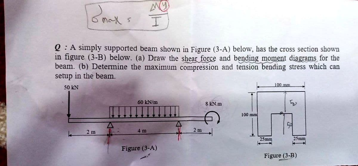
Q : A simply supported beam shown in Figure (3-A) below, has the cross section shown in figure (3-B) below. (a) Draw the shear force and bending moment diagrams for the beam. (b) Determine the maximum compression and tension bending stress which can setup in the beam. 100 mm 50 KN 60 kN/m 8 KN.m 100 mm 2 m 4 m 2 m 25mm 25mm Figure (3-A) Figure (3-B)
Q: he beam shown in the figure carries a distributed load and also a concentrated load. Taking into…
A: Part A) Determine the reaction at support by apply equilibrium condition
Q: Solve the following problem i- Draw the complete shearing force and bending moment diagram for the…
A:
Q: For the loaded beam shown in Figure Q6 below, consider section M-M and detemine the following: 6.1…
A: Given Data: Length of the beam, L=0.4+0.3+0.4=1.1 m
Q: A loaded, simply supported beam and its cross-section are shown in the figures below. 5 kN/m 20 mm:…
A: Solution:
Q: Consider the beam shown in (Figure 1). Suppose that the distributed load intensities w1 = 60 lb/ft…
A: The forces acting on the beam is shown below,
Q: Figure 2 below shows a 12 m length of beam with a pinned support at A and roller support at C. The…
A:
Q: For the wood beam shown in Figure A, assume L = 1.3 m and P = 11 kN. The beam cross section shown in…
A: Here we need to apply the concepts pf SFD and Bending of beams...
Q: Q1: A simply supported beam as shown in figure (1-A) below, having an I-cross sec has an over all…
A:
Q: Draw the shear force and bending moment diagram for a cantilever loaded as shown in the figure,…
A:
Q: Solve the following problem i- Draw the complete shearing force and bending moment diagram for the…
A:
Q: 3 For the simply supported beam shown in the figure, point (C) may represent a point of…
A: Take moment about the point A, From the vertical equilibrium of forces,
Q: Rectangular cross-section and width given the loading state in the figure Bending safety stress of…
A:
Q: Figure 1. 40 kN 30 kN/m 20 KN B K A -2m+ K 2m Re RA Figure 1. 85 mmm 68 mm Section K-K
A:
Q: For the wood beam shown in Figure A, assume L = 1.5 mand P = 15 kN. The beam cross section shown in…
A:
Q: Situation 12: The simply supported beam in FIGURE SOM-008 is fabricated by gluing together three 160…
A: For the given simply supported beam maximum bending stress in the planks = 24 MPa To determine…
Q: Draw the complete shearing force and bending moment diagrams for the beam shown in figure Fig.-1.…
A:
Q: The figure below shows a hollow circular beam with an outside diameter of 150 mm and a wall…
A:
Q: 5. A solid rectangular beam is loaded as shown in Figure Q5a. The beam is pin-supported at B and…
A:
Q: The cross-section of beam shown in Figure Q2 (centroid in red) is subjected to pure bending. Taking…
A:
Q: For the beam shown in figure below, draw the shear force and bending moment.
A:
Q: For the beam shown in below figure 1, sketch the shear force and bending momer diagrams. And…
A:
Q: The simply supported beam as shown in Figure 1 has the rectangular cross-section (b = 85 mm, h = 105…
A:
Q: 3-In the figure given below, P(load) and M(moment) effects from the mid point of the fixed beam from…
A: given data;load =Pmoment =MEI=constantlength of beam(l)=2Llets take reaction force at A=RA take…
Q: 4.5-3 /Draw the shear-force and bending-moment diagrams for a cantilever beam AB carrying a uniform…
A:
Q: aw the Normal Force Diagram. (b) Draw the shear force diagram. (c) Draw the bending moment…
A:
Q: beam ABCDE is 5 m in length and loaded as shown in Figure Q3. Draw the S.F. and B.M. diagrams for…
A:
Q: Q1: A simply supported beam as shown in figure (1-A) below, having an I-cross section, has an over…
A: At a time, we are restricted to solve only one question at a time. Please ask other question in…
Q: 7) Consider the beam in the figure below. Take w=50 kN/m. The 40 kN force makes an angle of 60…
A:
Q: 75 kN 10 kN/m A D B %3D %3D %3D %3D 10 m 2 m 2 m The beam shown in the figure carries a distributed…
A: Given data: Beam as shown above with the loading condition To determine: Support reaction…
Q: Q1: A simply supported beam as shown in figure (1-A) below, having an I-cross section, has an over…
A: Given dataUDL on 1.5m span UDL1.5 = 30kN/mPoints loads of each 20kN and 10kNUDL on 1m span UDL1 =…
Q: Consider the simple beam in Figure 7 with two concentrated loads, where AB-BC=CD=4m: 6kN 12kN 12m…
A:
Q: 3. For the beam shown in Figure 3 determine the following:- 1. The second moment of area of the…
A: Shear force is the is the summation of all the forces either to the left of the section or to the…
Q: For the loaded beam shown in Figure Q6 below, consider section M-M and determine the following: 6.1…
A:
Q: Draw a shear force diagram and a bending moment diagram for a cantilever beam AB subjected to an…
A:
Q: For the loaded beam shown in Figure Q6 below, consider section M-M and determine the following: 6.1…
A: Solution - First we will find out the reaction force developed at points A and D Then using the…
Q: A steel beam ABC carries a uniformly distributed load of w (kN/m) over the unsupported length BC, as…
A:
Q: For the simply supported beam subjected to the loads shown. Let a=3.00 m, b=4.00 m, PB = 30kN, and…
A:
Q: Example 1 The bar is subjected to a moment of M = 17.5 N.m. If r = 5 mm, determine the maximum…
A: Introduction: Bending stress is the typical stress that an item experiences when subjected to a…
Q: Q2: A simply supported beam shown in Figure (1-A) below, has the cross section shown in Figure (1-B)…
A: (a) To find: The shear force and bending moment diagram of the beam. FBD: The free body diagram of…
Q: Q/ The figure shows the vertical cross- section of a beam which at this section is subjected to a…
A: Answer: (a) The Bending stresses: ◆ Tensile stress : 1 MPa ◆ Compressive stress : 0.6 MPa (b) The…
Q: Q2: For the cantilever beam Shown in Figure 2 30 kN/m 20 kN.m В C D 1.5 m 1.5 m 2 m Figure 2 I. Find…
A:
Q: 5.8-6) A cantilever beam of length L = 2 m sup- ports a load P = 8.0 kN (see figure). The beam is…
A:
Q: 1. Draw shear force and bending moment diagrams for the beam shown in figure. 30kN 2m B 10KN/m C 10m
A: First calculate the reactions at the supports,
Q: (a) The Figure la show the cross-section of a beam. All dimension are in cm. 10 2 10 Figure la (i)…
A:
Q: Q) A simply supported beam shown is loaded as shown in figure l-1. It has the cross section as shown…
A:
Q: For the beam shown in figure below, draw the shearing force and bending moment diagrams showing the…
A:
Q: The shaft in Figure B1 is subjected to the concentrated forces shown. T sleeve bearings at A and B…
A:
Q: beam is loaded as shown in the figure. F = 2200 lb, b = 2 in. and h = 4 in. Determine the…
A: Given data:- Force (F) =2200lb b= 2 in h=4 in
Q: Figure 3 below shows a 16 m length of beam with a pinned support at A and roller support at C. The…
A: 1) Free body diagram of the beam and calculation of reaction forces The free body diagram of the…
Q: ter of the beam must be at least how many mm so that the amount of collapse that will occur at point…
A: We will find out the deflection at B due to point load and moment and equate it with permissible…
Step by step
Solved in 4 steps with 4 images
- The cross section of a sandwich beam consisting of fiberglass faces and a lightweight plastic core is shown in the figure. The width b of the beam is 50 mm, the thickness I of the faces is 4 mm, and the height hcof the core is 92 mm (total height A = 100 mm). The moduli of elasticity are 75 GPa for the fiberglass and 1.2 GPa for the plastic. A bending moment M = 275 N · m acts about the z axis. Determine the maximum stresses in the faces and the core using (a) the general theory for composite beams and (b) the approximate theory for sandwich beams.A wood beam reinforced by an aluminum channel section is shown in the figure. The beam has a cross section of dimensions 150 mm x 250 mm, and the channel has a uniform thickness of 6.5 mm. If the allowable stresses in the wood and aluminum are 8 M Pa and 38 M Pa, respectively, and if their moduli of elasticity are in the ratio 1 to 6, what is the maximum allowable bending moment for the beam?The cross section of a rectangular beam having a width b and height h is shown in part a of the figure. For reasons unknown to the beam designer, it is planned to add structural projections of width b/9 and height d/9 the top and bottom of the beam (see part b of the figure). For what values of d is the bending-moment capacity of the beam increased? For what values is it decreased?
- The cross section of a bimetallic strip is shown in the figure. Assuming that the moduli of elasticity for metals A and B are EA=168 GPa and EB= 90 GPa, respectively, determine the smaller of the two section moduli for the beam. (Recall that section modulus is equal to bending moment divided by maximum bending stress.) In which material does the maximum stress occur?The cross section of a composite beam made of aluminum and steel is shown in the figure. The moduli of elasticity are TA= 75 GPa and Es= 200 GPa. Under the action of a bending moment that produces a maximum stress of 50 M Pa in the aluminum, what is the maximum stress xs in the steel? If the height of the beam remains at 120 mm and allowable stresses in steel and aluminum are defined as 94 M Pa and 40 M Pa, respectively, what heights h and h. arc required for aluminum and steel, respectively, so that both steel and aluminum reach their allowable stress values under the maximum moment?Two identical, simply supported beams AB and CD are placed so that they cross each other at their midpoints (sec figure). Before the uniform load is applied, the beams just touch each other at the crossing point. Determine the maximum bending moments (mab)max* and (MCD)max beams AB and CD, respectively, due to the uniform load if the intensity of the load is q = 6.4 kN/m and the length of each beam is L = 4 m.
- A r o lukI f/frm f «m t ub e of ou t sid e d ia met er ^ and a copper core of diameter dxare bonded to form a composite beam, as shown in the figure, (a) Derive formulas for the allowable bending moment M that can be carried by the beam based upon an allowable stress <7Ti in the titanium and an allowable stress (u in the copper (Assume that the moduli of elasticity for the titanium and copper are Er- and £Cu, respectively.) (b) If d1= 40 mm, d{= 36 mm, ETl= 120 GPa, ECu= 110 GPa, o-Ti = 840 MPa, and ctqj = 700 MPa, what is the maximum bending moment Ml (c) What new value of copper diameter dtwill result in a balanced design? (i.e., a balanced design is that in which titanium and copper reach allow- able stress values at the same time).A cantilever beam AB having rectangular cross sections with varying width bxand varying height hxis subjected to a uniform load of intensity q (sec figure). If the width varies linearly with x according to the equation hx= bBxiL^ how should the height hxvary as a function of v in order to have a fully stressed beam? (Express hxin terms of the height hBat the fixed end of the beam.)A C 200 x 17.1 channel section has an angle with equal legs attached as shown; the angle serves as a lintel beam. The combined steel section is subjected to a bending moment M having its vector directed along the z axis, as shown in the figure. The cent roi d C of the combined section is located at distances xtand ycfrom the centroid (C1) of the channel alone. Principal axes yl and yvare also shown in the figure and properties Ix1,Iy1and 0pare given. Find the orientation of the neutral axis and calculate the maximum tensile stress exand maximum compressive stress if the angle is an L 76 x 76 x 6.4 section and M = 3.5 kN - m. Use the following properties for principal axes for the combined section:/^, = 18.49 X 10⁶ nrai4,/;| = 1.602 X 106 mm4, ep= 7.448*(CW),_r£ = 10.70 mm,andvf= 24.07 mm.
- The beam ABC shown in the figure is simply supported at A and B and has an overhang from B to C. The loads consist of a horizontal force P1= 4,0 kN acting at the end of a vertical arm and a vertical force P2= 8.0 kN acting at the end of the overhang, Determine the shear force Fand bending moment M at a cross section located 3,0 m from the left-hand support. Note: Disregard the widths of the beam and vertical arm and use centerline dimensions when making calculations, Find the value of load A that results in V = 0 at a cross section located 2.0 m from the left-hand support. If P2= 8.0 kN, find the value of load P1that results in M = 0 at a cross section located 2,0 m from the left-hand support.A beam supporting a uniform load of intensity q throughout its length rests on pistons at points A, C and B (sec figure). The cylinders are filled with oil and are connected by a tube so that the oil pressure on each piston is the same. The pistons at A and B have diameter d1and the piston at C has diameter D2. (a) Determine the ratio of d2to d1so that the largest bending moment in the beam is as small as possible. Under these optimum conditions, what is the largest bending moment Mmaxin the beam? What is the difference in elevation between point C and the end supports?A beam of square cross section (a = length of each side) is bent in the plane of a diagonal (see figure). By removing a small amount of material at the top and bottom corners, as shown by the shaded triangles in the figure, you can increase the section modulus and obtain a stronger beam, even though the area of the cross section is reduced. Determine the ratio ß defining the areas that should be removed in order to obtain the strongest cross section in bending. By what percent is the section modulus increased when the areas arc removed?