For the system shown in figure, voltages V2. V3 and angles 82 83 are calculated using Newton-Raphson method. shunt line charging admittances are neglected. All the values are given in per unit on 100MVA base. Calculate the complex power flows S12 and S32 in actual units. Z12 = 0.01+ j0.02 Z3 = 0.02+ j0.04 PL Slack bus V=1.0/0° V = 0.962 -1.67° V, = 0.882 - 5.48°
For the system shown in figure, voltages V2. V3 and angles 82 83 are calculated using Newton-Raphson method. shunt line charging admittances are neglected. All the values are given in per unit on 100MVA base. Calculate the complex power flows S12 and S32 in actual units. Z12 = 0.01+ j0.02 Z3 = 0.02+ j0.04 PL Slack bus V=1.0/0° V = 0.962 -1.67° V, = 0.882 - 5.48°

Power System Analysis and Design (MindTap Course List)
6th Edition
ISBN:9781305632134
Author:J. Duncan Glover, Thomas Overbye, Mulukutla S. Sarma
Publisher:J. Duncan Glover, Thomas Overbye, Mulukutla S. Sarma
Chapter3: Power Transformers
Section: Chapter Questions
Problem 3.41P: Consider the single-line diagram of the power system shown in Figure 3.38. Equipment ratings are...

Related questions
Question
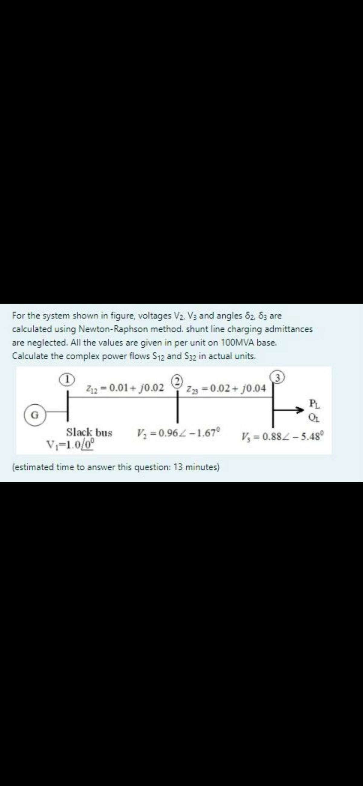
Transcribed Image Text:For the system shown in figure, voltages V2. V3 and angles 82, 8z are
calculated using Newton-Raphson method. shunt line charging admittances
are neglected. All the values are given in per unit on 100MVA base.
Calculate the complex power flows S12 and S32 in actual units.
Z12 = 0.01+ j0.02
Z3 = 0.02 + j0.04
PL
Slack bus
V=1.0/0°
V = 0.96L-1.67°
V, = 0.882-5.48°
(estimated time to answer this question: 13 minutes)
Expert Solution
This question has been solved!
Explore an expertly crafted, step-by-step solution for a thorough understanding of key concepts.

Step by step
Solved in 6 steps with 1 images

Recommended textbooks for you
Power System Analysis and Design (MindTap Course …
Electrical Engineering
ISBN:
9781305632134
Author:
J. Duncan Glover, Thomas Overbye, Mulukutla S. Sarma
Publisher:
Cengage Learning
Power System Analysis and Design (MindTap Course …
Electrical Engineering
ISBN:
9781305632134
Author:
J. Duncan Glover, Thomas Overbye, Mulukutla S. Sarma
Publisher:
Cengage Learning