
Database System Concepts
7th Edition
ISBN: 9780078022159
Author: Abraham Silberschatz Professor, Henry F. Korth, S. Sudarshan
Publisher: McGraw-Hill Education
expand_more
expand_more
format_list_bulleted
Related questions
Question
Given the following Combinational circuit, Use Verilog HDL on Quartus tool to
1. Write a Verilog HDL code to describe the module DCDR2×4 // this module name must be your last name ( younis
2. Write a Verilog HDL code to describe the whole system structurally from its subsystems
// this module name must be your university number ( 1181230)
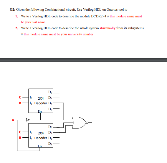

Transcribed Image Text:Q2: Given the following Combinational circuit, Use Verilog HDL on Quartus tool to
1. Write a Verilog HDL code to describe the module DCDR2×4 // this module name must
be your last name
2. Write a Verilog HDL code to describe the whole system structurally from its subsystems
/l this module name must be your university number
2X4
D,
B
I Decoder D,
D3
En
A
Do
Io
2X4
DI
B
I, Decoder D,
D3
En
Expert Solution
This question has been solved!
Explore an expertly crafted, step-by-step solution for a thorough understanding of key concepts.

This is a popular solution

Trending nowThis is a popular solution!

Step by stepSolved in 2 steps with 1 images

Knowledge Booster


Learn more about
Need a deep-dive on the concept behind this application? Look no further. Learn more about this topic, computer-science and related others by exploring similar questions and additional content below.Similar questions
- Draw block diagrams to implement a 4 to 1 with 4 bits multiplexer. The data input lines are 4 bits wide. Please decide how many selects do you need. And write the final equation for inputs and output in both your report and block diagram. Do the simulation and save the screenshot into your report.arrow_forwardDraw a circuit schematic for the following RTL circuit description st : R1 ← R1 + R3, R2 ← R2 +1 st: R30 st: R3 R1, R2 ← R1 st: R3 R2 + R3arrow_forwardThe programmable connections in PLDs are implemented using a variety of process technologies; provide six examples.arrow_forward
- Design a BCD (Binary Coded Decimal) to Excess – 3 code converter circuit. Implement using 7408, 7432, and 7486 in tinkercad. Even a photo of it will surely help me in my review. Thank you so much!!arrow_forwardFigure Q7 describes a Linear Feedback Shift Register (LFSR). Draw the equivalent schematic diagram of the system based on an off-the-shelf shift register, clearly showing the number of exclusive-OR gates needed to construct it. LIBRARY ieee; USE ieee.std logic_1164.all; entity lfsr is CLK, RESET: in STD LOGIC; Q: out STD LOGIC_VECTOR (5 downto 0) ); port ( end lfsr; architecture behavior of lfsr is begin process (CLK,RESET) begin if RESET='1' then Q <= "000001"; else Q <= ( Q(3) xor Q(2) xor Q(0) ) & Q(5 downto 1); end if; end process; end behavior;arrow_forwardConsider a circuit designed as follows: • one 1-bit register (like those discussed in class), with an attached clock • one not gate • wire A connects the register's ouput and the not's input • wire B connects the not's output and the register's input If we put a 1 onto wire B: A. wire A gets a 0 immediately B. wire A gets a 0 after the short delay it takes the gates in the register to finish work C. wire A gets a 0 after the next clock tick D. wire A gets a 1 immediately E. wire A gets a 1 after the short delay it takes the gates in the register to finish work O F. wire A gets a 1 after the next clock tickarrow_forward
- Assume we are writing a testbench for a sequential circuit that has three control inputs (cA, cB, cC) and a periodic clock (clk). If we define CLK_PERIOD as a localparameter with a value of 50 (nsec), write the testbench segment that would ensure all possible combinations of the control inputs were tested on a clock rising edge. This is can be done more elegantly if you define each time step in terms of the constant CLK_PERIOD. Your answer should include the statements that define clk, cA, cB, and cC over time. Hint: think of how you would show all combinations of three variables on a truth table and replicate that over time, where each combination is held over a timespan with a clock triggering edge.arrow_forwardDesign the interface for a positive logic switch to TM4C123GXL Port A pin 7. Show formulas and calculations for each circuit element. Draw the circuit schematics with components labelled with their names and values. Write the C code as a function to initialize the port for interfacing the switch. Write a function to read the data value of Port A pin 7. Comment your code to explain each initialization step clearly.arrow_forwardDraw a circuit to implement a switching network with two data inputs (A and B), two data outputs (C and D), and a control input (S). If S=1, the network is in pass-through mode: C=A and D=B. If S=0, the network is in crossing mode: C=B, and D=A. Use the most reasonable combinational building blocks or gates. Label the inputs and outputs.arrow_forward
- In verilog a counter must be developed from 0 to 9999 with a reset and parallel loading. The reset will be a button in charge of returning the count to 0 when pressed.For this practice, the implemented circuit will only use a 7-segment BCD converter module, which will have to be managed between the different 7-segment displays at a given frequency.arrow_forwardDraw the logic diagram of the digital circuit specified by the following Verilog description:arrow_forwardYou have to design a fast multiplier: the operands are A1A0 and B1B0. Thendesign a fast adder for the same operands. Both circuits have to fit in the same IC;the operands are applied and the sum as well as the multiplication appear at theoutput. Obviously, your answer has to be correct AND economical.arrow_forward
arrow_back_ios
SEE MORE QUESTIONS
arrow_forward_ios
Recommended textbooks for you
- Database System ConceptsComputer ScienceISBN:9780078022159Author:Abraham Silberschatz Professor, Henry F. Korth, S. SudarshanPublisher:McGraw-Hill Education
 Starting Out with Python (4th Edition)Computer ScienceISBN:9780134444321Author:Tony GaddisPublisher:PEARSON
 Digital Fundamentals (11th Edition)Computer ScienceISBN:9780132737968Author:Thomas L. FloydPublisher:PEARSON
  C How to Program (8th Edition)Computer ScienceISBN:9780133976892Author:Paul J. Deitel, Harvey DeitelPublisher:PEARSON
 Database Systems: Design, Implementation, & Manag...Computer ScienceISBN:9781337627900Author:Carlos Coronel, Steven MorrisPublisher:Cengage Learning
 Programmable Logic ControllersComputer ScienceISBN:9780073373843Author:Frank D. PetruzellaPublisher:McGraw-Hill Education
Database System Concepts
Computer Science
ISBN:9780078022159
Author:Abraham Silberschatz Professor, Henry F. Korth, S. Sudarshan
Publisher:McGraw-Hill Education
Starting Out with Python (4th Edition)
Computer Science
ISBN:9780134444321
Author:Tony Gaddis
Publisher:PEARSON
Digital Fundamentals (11th Edition)
Computer Science
ISBN:9780132737968
Author:Thomas L. Floyd
Publisher:PEARSON
C How to Program (8th Edition)
Computer Science
ISBN:9780133976892
Author:Paul J. Deitel, Harvey Deitel
Publisher:PEARSON
Database Systems: Design, Implementation, & Manag...
Computer Science
ISBN:9781337627900
Author:Carlos Coronel, Steven Morris
Publisher:Cengage Learning
Programmable Logic Controllers
Computer Science
ISBN:9780073373843
Author:Frank D. Petruzella
Publisher:McGraw-Hill Education