he following diagram shows some registers like processor registers R1 and R2, Program counter PC and Index Register XR along with their corresponding values. It also shows a memory with some instructions like instruction A and next instruction. The memory holds instruction B which consists of four fields as given above. First field of instruction represents the addressing Mode (I), second field specifies Opcode (operation code) ADD representing operation addition, the third field represents Address field 1 and the fourth field represents Address field 2. Consider the following addressing modes, evaluate the result of execution of above instruction by giving steps of evaluation for each addressing mode for the scenario given above. Ø Immediate Mode Ø Direct Mode Ø Register Ø Relative Mode Ø Index Mode Choose your own values for variables k – w, T1, T2. Choose any one of the given value for T3 (200 or 300).


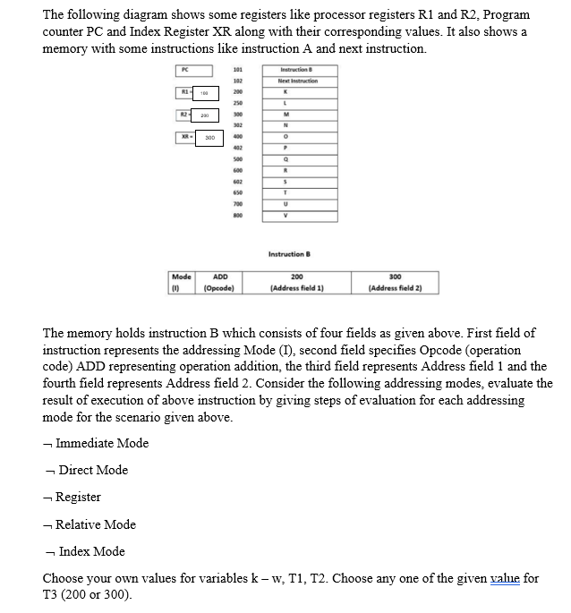
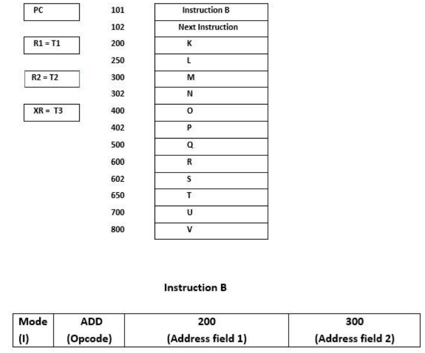
The following diagram shows some registers like processor registers R1 and R2, Program counter PC and Index Register XR along with their corresponding values. It also shows a memory with some instructions like instruction A and next instruction.
The memory holds instruction B which consists of four fields as given above. First field of instruction represents the addressing Mode (I), second field specifies Opcode (operation code) ADD representing operation addition, the third field represents Address field 1 and the fourth field represents Address field 2. Consider the following addressing modes, evaluate the result of execution of above instruction by giving steps of evaluation for each addressing mode for the scenario given above.
Ø Immediate Mode
Ø Direct Mode
Ø Register
Ø Relative Mode
Ø Index Mode
Choose your own values for variables k – w, T1, T2. Choose any one of the given value for T3 (200 or 300).


Trending now
This is a popular solution!

Step by step
Solved in 2 steps


