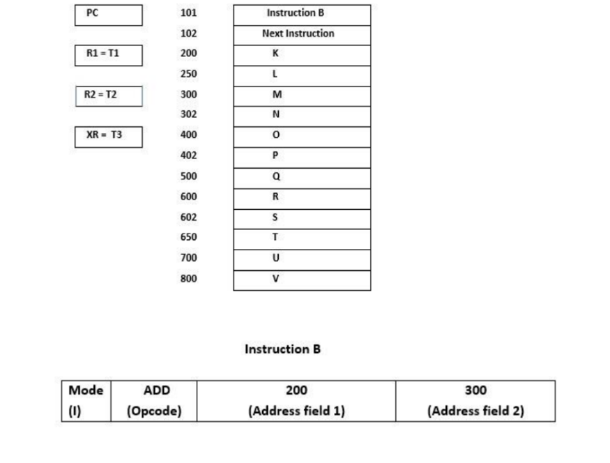
The following diagram shows some registers like processor registers R1 and R2, Program counter PC and Index Register XR along with their corresponding values. It also shows a memory with some instructions like instruction A and next instruction. Ne Instrution Mede ADD 10pade (Addres field 1) (Addres field 2) The memory holds instruction B which consists of four fields as given above. First field of instruction represents the addressing Mode (I), second field specifies Opcode (operation code) ADD representing operation addition, the third field represents Address field 1 and the fourth field represents Address field 2. Consider the following addressing modes, evaluate the result of execution of above instruction by giving steps of evaluation for each addressing mode for the scenario given above. - Immediate Mode - Direct Mode - Register - Relative Mode - Index Mode Choose your own values for variables (v– w), T1, T2. Choose any one of the given value for T3 (200 or 300). V=600 W=700 T1=100 T2=200 T3=300

Systems Architecture
7th Edition
ISBN:9781305080195
Author:Stephen D. Burd
Publisher:Stephen D. Burd
Chapter4: Processor Technology And Architecture
Section: Chapter Questions
Problem 2PE: If a microprocessor has a cycle time of 0.5 nanoseconds, what’s the processor clock rate? If the...
icon
Related questions
Question

The following diagram shows some registers like processor registers R1 and R2, Program counter PC and Index Register XR along with their corresponding values. It also shows a memory with some instructions like instruction A and next instruction.

The memory holds instruction B which consists of four fields as given above. First field of instruction represents the addressing Mode (I), second field specifies Opcode (operation code) ADD representing operation addition, the third field represents Address field 1 and the fourth field represents Address field 2. Consider the following addressing modes, evaluate the result of execution of above instruction by giving steps of evaluation for each addressing mode for the scenario given above.

Ø Immediate Mode

 Ø Direct Mode

Ø Register

Ø Relative Mode

 Ø Index Mode

Choose your own values for variables (v – w), T1, T2. Choose any one of the given value for T3 (200 or 300).

V=600

W=700

T1=200

T2=200

T3=300
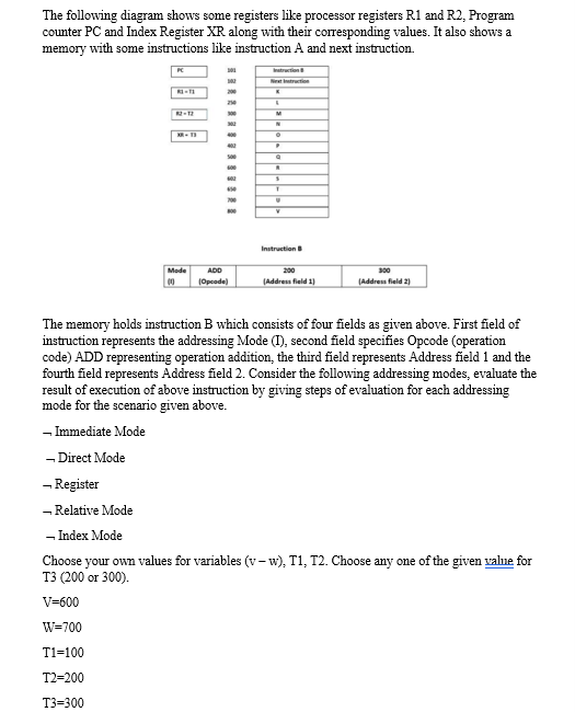
The following diagram shows some registers like processor registers R1 and R2, Program
counter PC and Index Register XR along with their corresponding values. It also shows a
memory with some instructions like instruction A and next instruction.
Iatrution
Nit trt
Instruction
Mode
ADD
200
300
(Opeode)
(Address field 1)
(Address field 2)
The memory holds instruction B which consists of four fields as given above. First field of
instruction represents the addressing Mode (M), second field specifies Opcode (operation
code) ADD representing operation addition, the third field represents Address field 1 and the
fourth field represents Address field 2. Consider the following addressing modes, evaluate the
result of execution of above instruction by giving steps of evaluation for each addressing
mode for the scenario given above.
- Immediate Mode
- Direct Mode
- Register
- Relative Mode
- Index Mode
Choose your own values for variables (v- w), T1, T2. Choose any one of the given value for
T3 (200 or 300).
V=600
W=700
T1=100
T2=200
T3=300
Transcribed Image Text:The following diagram shows some registers like processor registers R1 and R2, Program counter PC and Index Register XR along with their corresponding values. It also shows a memory with some instructions like instruction A and next instruction. Iatrution Nit trt Instruction Mode ADD 200 300 (Opeode) (Address field 1) (Address field 2) The memory holds instruction B which consists of four fields as given above. First field of instruction represents the addressing Mode (M), second field specifies Opcode (operation code) ADD representing operation addition, the third field represents Address field 1 and the fourth field represents Address field 2. Consider the following addressing modes, evaluate the result of execution of above instruction by giving steps of evaluation for each addressing mode for the scenario given above. - Immediate Mode - Direct Mode - Register - Relative Mode - Index Mode Choose your own values for variables (v- w), T1, T2. Choose any one of the given value for T3 (200 or 300). V=600 W=700 T1=100 T2=200 T3=300
PC
101
Instruction B
102
Next Instruction
R1 = T1
200
K
250
L
R2 = T2
300
M
302
XR = T3
400
402
P
500
Q
600
R
602
S
650
700
800
V
Instruction B
Mode
ADD
200
300
(1)
(Opcode)
(Address field 1)
(Address field 2)
Transcribed Image Text:PC 101 Instruction B 102 Next Instruction R1 = T1 200 K 250 L R2 = T2 300 M 302 XR = T3 400 402 P 500 Q 600 R 602 S 650 700 800 V Instruction B Mode ADD 200 300 (1) (Opcode) (Address field 1) (Address field 2)
Expert Solution
steps

Step by step

Solved in 2 steps

Blurred answer
Knowledge Booster
Fundamentals of Input and Output Performance
Learn more about
Need a deep-dive on the concept behind this application? Look no further. Learn more about this topic, computer-science and related others by exploring similar questions and additional content below.
Similar questions
  • SEE MORE QUESTIONS
Recommended textbooks for you
Systems Architecture
Computer Science
ISBN:
9781305080195
Author:
Stephen D. Burd
Publisher:
Cengage Learning